
Frequency Counter and Timer
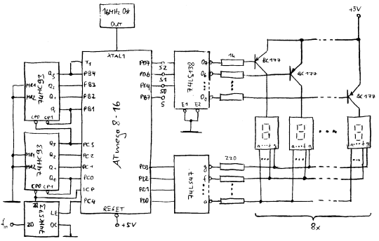
The circuit described offers a versatile frequency counter and timer functionality, with a resolution that is adaptable depending on the operational mode. In counter mode, the device is capable of handling frequencies up to 100 MHz while maintaining a 1 Hz resolution, making it suitable for high-speed applications. Conversely, in timer mode, the resolution is significantly enhanced, allowing for measurements as precise as 0.0000001 Hz, albeit limited to frequencies up to 1 Hz.
The implementation of a sliding window calculation method allows the device to update its frequency readings multiple times per second, enhancing responsiveness. This feature is particularly beneficial in applications where frequency stability and quick response times are critical.
For in-circuit programmability of the AVR microcontroller, careful consideration of the circuit design is necessary. The use of 47 kΩ resistors to isolate third-party programming connections is a prudent design choice that minimizes interference and protects the integrity of the programming signals. The combination of these resistors with the Mega8 gate capacitance forms a low-pass filter that helps to stabilize the signals during programming, ensuring reliable operation.
Software compensation for settling time is employed to further enhance performance, allowing the external counter to operate effectively despite any potential delays introduced by the circuit.
The test board assembly, as depicted in the accompanying image, showcases the complete counter circuit, with the exception of the 7-segment display components, which are housed on a separate board for ease of integration. The connections for digit selection and 7-segment code transmission are clearly defined, facilitating straightforward assembly and troubleshooting.
This final board design is optimized for integration into the intended device, featuring dedicated connectors for power supply, 7-segment display code, digit selection, in-circuit programming, and TTL signal input. This comprehensive approach ensures that the circuit is both functional and adaptable, meeting the demands of various electronic applications.In counter mode it provides 1Hz resolution up to 100Mhz. In timer mode maximum resolution is 0. 0000001 Hz up to 1Hz. Resolution is reduced by one digit for each additional decade. Multiple frequency updates per second by employing a sliding window for calculation. In case the AVR should be programmable in circuit, a few modifications must be made. In essence all third parties on wires used for programming are isolated using 47k resistors. The resistors in combination with Mega8 gate capacity create a low pass. This is software compensated using increased settling time for the external counter. This picture shows the test board with the full counter circuit except the 7 segment LEDs. Those are already mounted and soldered on a separate board. The wires on the top right connect to it. (One connector for digit selection and one for the actual 7 segment code. ) This is the final board that will be put into the device. It has connectors for power, 7 segment code, digit selection, in circuit programming and TTL signal input. 🔗 External reference
Related Circuits
Power the frequency counter and adjust the coarse (top pot) and fine (bottom pot) controls to display zero frequency. Turn the pots counter-clockwise to achieve a zero reading. Occasionally, the counter may show only squares without digits. If this...
The 7208 seven-metric system counter is utilized as a frequency meter. It features a latch and multiplexing function and incorporates a direct drive circuit along with a display driver circuit. The 7207 IC divides the output frequency of a...

This is a programmable clock timer circuit that utilizes individual LEDs to indicate hours and minutes. Twelve LEDs are arranged in a circle to represent the 12 hours of a clock face, while an additional 12 LEDs are positioned...
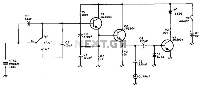
This circuit utilizes a Colpitts oscillator (Q1) paired with a buffer amplifier (Q2) to facilitate crystal testing. SI allows for the selection of three load conditions: series (S), 20 pF, and 32 pF. It is essential to keep the...
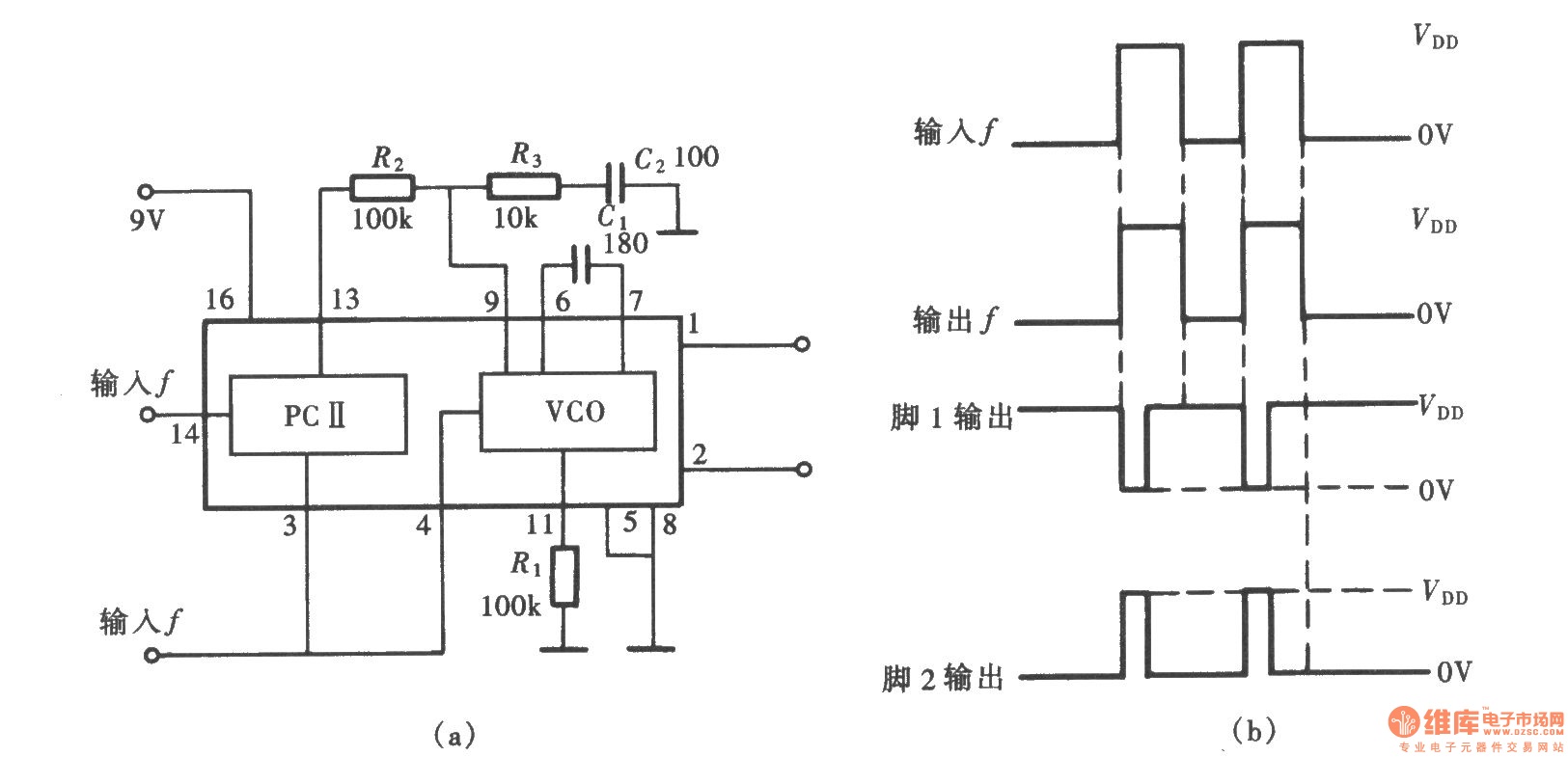
A frequency signal tracking circuit is implemented using a phase-locked loop (PLL) configuration, which is a fundamental application of the CD4046 integrated circuit. The circuit, illustrated in the accompanying chart, utilizes the CD4046 to form a PLL that effectively...
A signal conditioner for a pH meter probe requires high input impedance. The signal conditioning of the pH meter probe is achieved by incorporating a buffer. The design of a signal conditioner for a pH meter probe is critical for...
Warning: include(partials/cookie-banner.php): Failed to open stream: Permission denied in /var/www/html/nextgr/view-circuit.php on line 713
Warning: include(): Failed opening 'partials/cookie-banner.php' for inclusion (include_path='.:/usr/share/php') in /var/www/html/nextgr/view-circuit.php on line 713