
Code practice oscillator
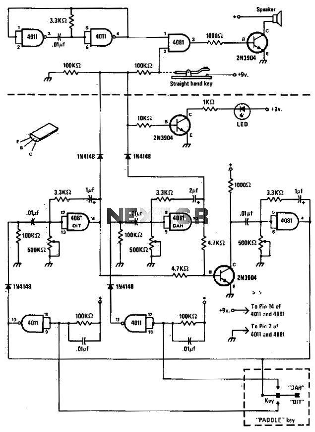
The described circuit integrates two primary components: a basic oscillator and an automatic keyer, each serving distinct functions within the overall design. The basic oscillator is responsible for generating a consistent frequency output, which is essential for various applications, including signal transmission in communication devices. This oscillator typically employs a simple RC (resistor-capacitor) or LC (inductor-capacitor) network to establish its oscillation frequency, ensuring stable and reliable performance.
The automatic keyer, situated below the dashed line, is designed to facilitate automated Morse code transmission. This component can interpret input from two types of keys: a straight hand key, which is a simple mechanical switch, and a paddle key, which allows for more nuanced control over the timing and spacing of the Morse code signals. The automatic keyer processes the input from these keys to produce a series of on-off signals that correspond to the Morse code characters being transmitted.
The integration of both the oscillator and the automatic keyer allows for efficient operation in transmitting Morse code without the need for continuous manual input. This design is particularly beneficial for amateur radio operators and other communication enthusiasts who require reliable and automated communication capabilities. The circuit can be further enhanced with additional features such as adjustable speed control for the keyer, allowing operators to customize the transmission speed to their preference.The circuit consists of a basic oscillator (above dashed line) and an automatic keyer (below dashed line) The unit can be used with a straight hand key or a paddle key for automatic operation. 🔗 External reference
Related Circuits
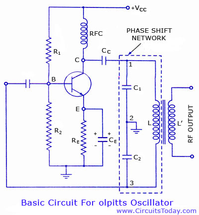
Colpitts oscillator circuit diagram and theory. Colpitts oscillator frequency equation. Colpitts oscillator using transistor. Colpitts oscillator using op-amp. The Colpitts oscillator is a type of electronic oscillator that generates sine waves and is widely used in various applications such as...
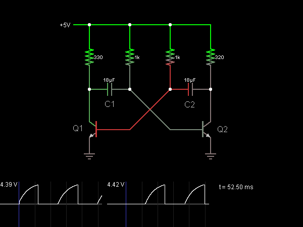
This circuit functions as an astable multivibrator, also known as an oscillator. The two transistors are interconnected in a manner that allows the circuit to alternate between two states. In one state, the base of transistor Q1 is approximately...
A variable audio oscillator operates within a frequency range of 20 hertz to 20 kilohertz. The circuit utilizes an Intersil 8038 waveform generator, which is designed in a 14-pin dual in-line package (DIP). The variable audio oscillator circuit is designed...
Surround Sound Decoder circuit diagram. The circuit's operation begins when the stereo sound signal carries surround sound information through the master volume section. This drives the Left channel (Lch), which is connected to Model TL072 IC1A and IC1B, with...
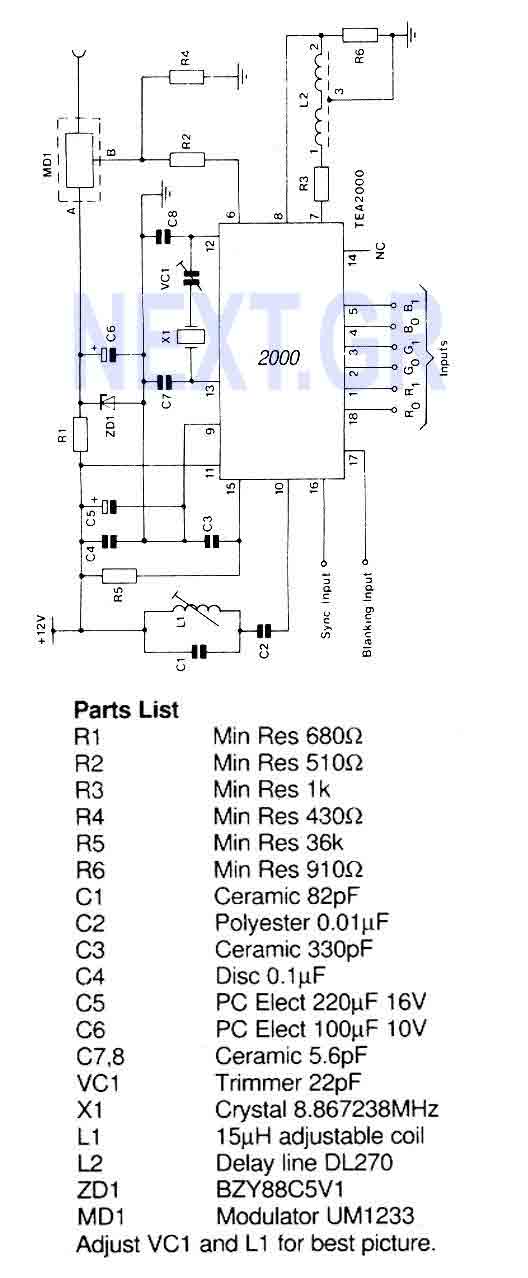
A PAL color encoder and video summer which requires just composite sync and composite blanking inputs, and a 6-bit binary coded input giving the color information. The inputs are organized as 2 bits per primary color with gamma correction...
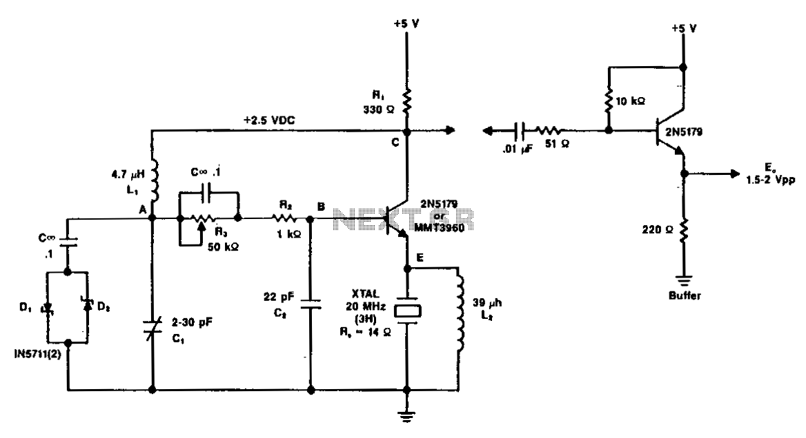
A typical circuit operating at 20 MHz is illustrated. The crystal, featuring an internal series resistance (Rs) of 14 ohms, oscillates at its third harmonic frequency. Diode clamps D1 and D2 ensure constant amplitude control. The transistor functions continuously...