
PC Relay Controller
The relay controller circuit utilizes the Basic Stamp I microcontroller, which interfaces with a PC through the serial port. The Basic Stamp I is programmed to handle commands received from the Visual Basic 5 application, which serves as the user interface for controlling the relays. The circuit can control up to two relays, allowing for the activation or deactivation of devices such as lights or motors.
The schematic consists of the Basic Stamp I connected to the PC's serial port, with the necessary connections established through a standard RS-232 interface. The Basic Stamp I's output pins are connected to the relay control inputs. Each relay is typically driven by a transistor to ensure that the microcontroller can safely control the higher current required by the relay coils.
The relay module should include flyback diodes connected in parallel with the relay coils to protect the microcontroller from voltage spikes generated when the relay is switched off. The circuit may also include resistors to limit the base current to the transistors and ensure proper operation.
Once the PC-Relay software is installed, it allows the user to select the appropriate COM port for the serial communication. The interface provides a straightforward method for sending commands to the Basic Stamp I, which in turn activates or deactivates the connected relays based on user input. This setup serves as an effective testing platform before proceeding to larger relay circuits, ensuring that all components function correctly and that the communication between the PC and the Basic Stamp I is reliable.This project shows you how to build a relay controller using the Basic Stamp I interfaced to the PC serial port. The Visual Basic 5 software developed for the interface lets you interact with the Basic Stamp to turn ON/OFF up to (2) relays attached to the Basic Stamp I/O pins.
As shown below in the screen capture of PC-Relay, it`s easy to select the desired com port using the drop-down menu. Once you have installed the PC-Relay software you`re ready to build the circuit shown above. This is a handy & quick circuit that will let you test everything before you build the bigger (relay) circuit. If everything works, i.e.. you can contr 🔗 External reference
Related Circuits
Sometimes, for a variety of reasons, it would be nice to vary the width of the sound stage when listening to stereo recordings. Although technically this is anything but hi-fi, it is a useful addition to PC speakers, or...
This circuit is a church bell controller. Basic component is an ATmega32 microcontroller. At the circuit 1 24LC32 EEPROM memory is being used. As control, a menu is created that appears on a 4x20 LCD (Liquid Crystal Display). The...
This PWM controller circuit is suitable for managing small motors with a maximum current consumption of 2A. For higher currents, additional cooling is required. The PWM (Pulse Width Modulation) controller circuit is designed to efficiently control the speed of small...
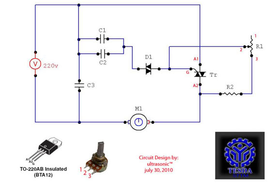
This circuit functions as a motor controller, allowing for easy control and variation of the RPM and phase of an AC motor. The power source is directly 220VAC, and it can handle a load of approximately 1 horsepower AC...
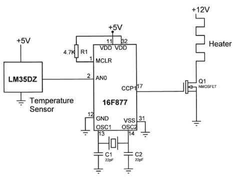
The electrical circuit diagram of this temperature control circuit consists of a 3-pin analog temperature sensor (LM35DZ), a built-in A/D converter microcontroller (PIC16F877), and the heater driver (IRL1004). The temperature control circuit utilizes the LM35DZ, a precision analog temperature sensor...
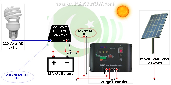
A solar charge controller is an electronic device used in solar system installations to regulate the amount of charge directed toward a battery from a solar panel. Charge controllers come in various types and ratings. The term "charge controller"...