
L200 Regulator Power Supply
The L200 voltage regulator is a versatile and adjustable linear regulator designed for various power supply applications. It can deliver output voltages ranging from 3V to 32V and can handle output currents up to 2A, making it suitable for a wide range of electronic devices. The circuit typically includes the L200 integrated circuit, along with external components such as resistors, capacitors, and diodes to optimize performance and stability.
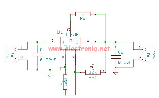
In a typical L200 power supply circuit, the input voltage is applied to the L200 IC, which regulates it to the desired output voltage. The output voltage can be adjusted using a pair of resistors configured as a voltage divider. The feedback pin of the L200 monitors the output voltage, ensuring that it remains stable despite variations in load current or input voltage.
Capacitors are often included at the input and output of the regulator to filter out noise and stabilize the voltage. An additional bypass capacitor may be connected to the feedback pin to enhance transient response. Protection features such as thermal shutdown and current limiting are integrated into the L200, safeguarding the circuit from overload conditions.
The L200 regulator is commonly used in applications requiring a stable power supply, such as in audio equipment, microcontroller circuits, and testing setups. Its ability to provide adjustable output voltage and current makes it a valuable component in many electronic designs. Proper layout and component selection are essential for achieving optimal performance and reliability in the final application.The following circuit shows about L200 Regulator Power Supply Circuit Diagram. Features: used in power supply with voltage and current .. 🔗 External reference
Related Circuits
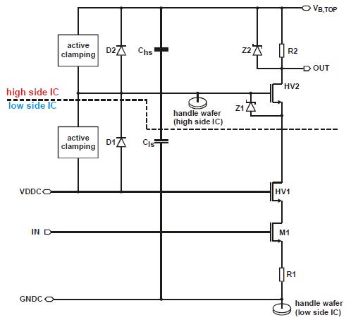
Integration of 1200V SOI gate driver ICs into a medium power IGBT module package. A novel approach for medium power applications. The integration of 1200V Silicon-On-Insulator (SOI) gate driver Integrated Circuits (ICs) into medium power Insulated Gate Bipolar Transistor (IGBT)...
This project involved designing an audio amplifier capable of delivering substantial output power with a minimal number of components while maintaining quality. The power amplifier section consists of three transistors and a few resistors and capacitors configured in a...
The first essential component for any workshop or lab is a power supply. When experimenting with various electronic circuit designs, having a flexible and adjustable power supply simplifies the process. Presented here is a design for an adjustable power...
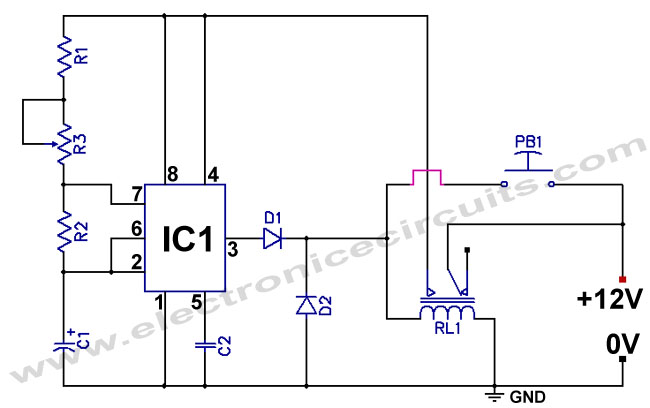
The standard 555 timer circuit consumes power from the battery even when the start push-button (PB1) is not pressed, due to a potential divider created by three 5kΩ resistors within the integrated circuit (IC). This power consumption, referred to...
The objective is to enhance information transmission through the distribution of articles. Please contact us via email at [email protected] within 15 days if there are any issues related to article content, copyright, or other concerns. Prompt action will be...
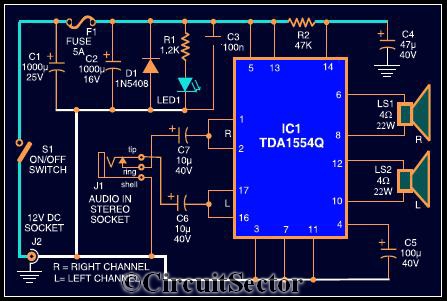
The circuit diagram illustrates a robust stereo amplifier capable of delivering 22W of power. It is based on the widely used single-chip audio power amplifier TDA1554Q (IC1), which is configured as two 22W stereo bridge amplifiers. While listening to...
Warning: include(partials/cookie-banner.php): Failed to open stream: Permission denied in /var/www/html/nextgr/view-circuit.php on line 713
Warning: include(): Failed opening 'partials/cookie-banner.php' for inclusion (include_path='.:/usr/share/php') in /var/www/html/nextgr/view-circuit.php on line 713