
Crystal testing

A simple crystal testing circuit can be designed using a few essential components, typically including a power source, a resistor, a capacitor, and an LED or a multimeter for indication. The primary function of this circuit is to determine the resonant frequency of the crystal and to check if it is functioning correctly.
The circuit can be structured as follows:
1. **Power Source**: A DC power supply, often in the range of 5V to 12V, can be used to power the circuit.
2. **Resistor**: A resistor (R1) can be connected in series with the crystal to limit the current flowing through it. The value of the resistor can vary, but a common choice is around 1kΩ to 10kΩ.
3. **Crystal**: The crystal under test is connected in parallel with a capacitor (C1). The value of the capacitor should be chosen based on the expected frequency of the crystal. A capacitor value of around 10nF to 100nF is often suitable.
4. **LED Indicator**: An LED can be connected in series with a current-limiting resistor (R2) to provide a visual indication of the crystal's operation. When the circuit is powered, if the crystal oscillates correctly, the LED will blink or illuminate.
5. **Multimeter**: For more precise testing, a multimeter can be connected to measure the frequency output from the circuit. This allows for a more accurate assessment of the crystal's performance.
The circuit is assembled on a breadboard for prototyping. The connections should be made carefully to avoid short circuits. Once assembled, powering the circuit should result in the LED lighting up if the crystal is functioning properly. If the LED does not light up or if the multimeter does not register the expected frequency, further investigation may be required to determine if the crystal is faulty.
This simple circuit provides an effective means for hobbyists and engineers to test and verify the functionality of various crystals in electronic applications.Can anyone point me in the direction of a simple useable circuit i can build for testing crystals? I have seen loads of circuits as i am googling.. 🔗 External reference
Related Circuits
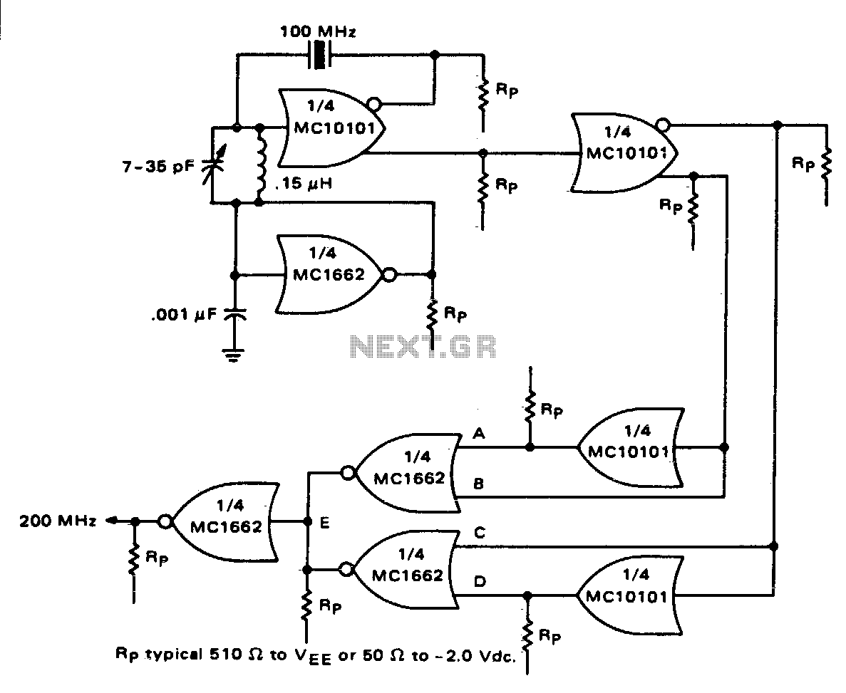
One section of the MC10101 is configured as a 100 MHz crystal oscillator, with the crystal placed in series within the feedback loop. An LC tank circuit is utilized to tune the 100 MHz harmonic of the crystal, which...
An oscillator is an amplifier with a feedback loop from output to input. The Barkhausen criteria state that for oscillation to occur, the product of the gains around a loop must be equal to or greater than unity, and...
The schematic illustrates the division of a crystal oscillator signal by the crystal frequency to achieve a precise 1-second time base with an accuracy of 0.01%. Two cascaded 12-stage counters (CD4040) create a 24-stage binary counter, with specific bits...
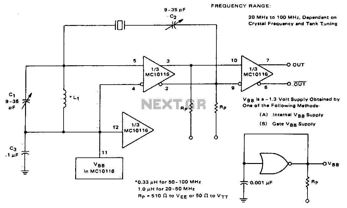
This circuit utilizes an adjustable resonant tank circuit that ensures operation at the desired crystal overtone. Capacitor C1 and inductor L1 form the resonant tank circuit, which can be adjusted to achieve a resonant frequency ranging from approximately 50...
Here exists a small collection from three generators, which use crystals for the basic production of oscillations. Each generator uses a different topology of circuit for the production of oscillations. The described circuit features three distinct oscillators, each utilizing a...
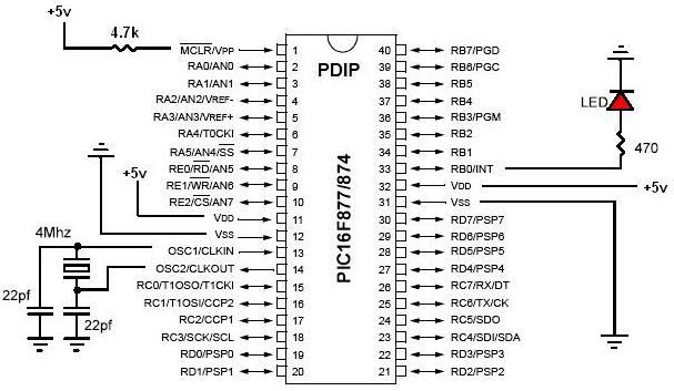
PIC development/testing board. This is a PCB design for a basic PIC16F877 development board. All that is required is a 4 MHz crystal, two 22 pF capacitors, and one 4.7 kΩ resistor. The PIC16F877 development board is designed to facilitate...