
Color display circuit
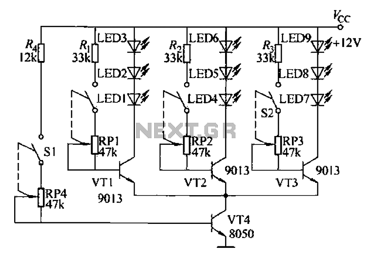
The circuit utilizes a series of transistors to control the brightness of red, green, and blue LEDs, which together create a full spectrum of colors through additive color mixing. The transistors (VT1, VT2, VT3) serve as switches that regulate the current flowing to each LED. The adjustment of the base bias resistors (RP1 and RP4) allows for fine-tuning of the LED brightness, enabling the educator to demonstrate the effects of varying color intensities and the resulting color combinations.
In practical applications, the circuit can be integrated into educational setups where students can interactively learn about color synthesis. By adjusting the resistors, they can observe firsthand how changes in the current affect the brightness of each LED, thereby gaining a deeper understanding of how colors are synthesized in color television technology. This hands-on approach not only enhances learning but also demystifies the technical aspects of color reproduction in electronic displays. Overall, the circuit serves as a valuable educational tool, bridging theoretical concepts with practical demonstrations in the field of electronics and color science. Colour in teaching, in order to allow students to understand the principle of color TV color synthesis. This circuit can be beneficial to use visual teaching, realistic reprodu ction of color signals received good teaching. Thus breaking the color synthesis abstraction. (1) Working principle of the circuit shown in Fig. It is away from the circuit according to the TV imaging using light emitting diode color synthesis circuit. FIG VT1 red light emitting diode driving circuit, VD1 ~ VD3 ultra-high brightness red LED, operating current is provided in terms of o ~ 30mA (depending on the characteristics of the light emitting diode may be), R., RP1 is VT1 base bias resistor, adjusting RP1, can change the flow through the light emitting diode operating current can be changed by a red LED diode emission luminance.
VT2 green light emitting diode driving road. VT3 for the blue light-emitting diode driving circuit, VT4 as a light adjustment circuit. R4, RP4 for the VT4 base bias circuit. RP4 adjustment (ie adjustment of VT4 collector current), you can change the flow through the red, green and blue light-emitting tube current and, therefore, changes the three color brightness light-emitting tube.
Related Circuits
The output level was set to 3.8V peak to peak. The initial objective was to compare several different operational amplifiers (op-amps) before further optimizing the circuit. The op-amps evaluated were the TL072, LM4562, and OPA2134. The distortion spectra are...
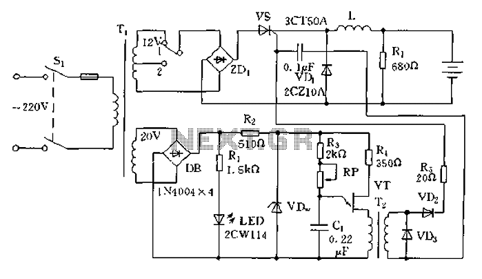
The circuit operates on the principle of a transformer, bridge rectifier, and conditioning for battery charging. The charging current can be adjusted to approximately 12V at 100A. For battery charging, a charging rate of 10 hours requires a charging...
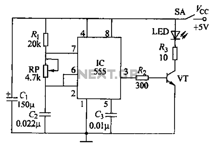
The circuit utilizes a 555 timer integrated circuit along with a transistor (VT) and several external components to create a multivibrator circuit. The charge and discharge time constants, Ti and T2, are defined, where Ti is approximately 0.7 times...
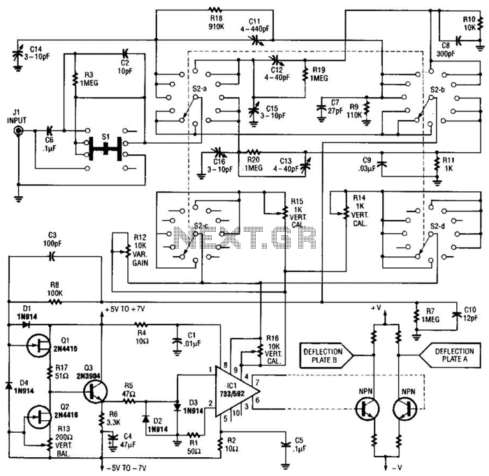
An oscilloscope front-end amplifier can be constructed using low-cost transistors and video amplifier integrated circuits (ICs). This preamplifier utilizes a FET input along with compensated attenuators, achieving an approximate bandwidth of 100 MHz, which is sufficient for most general-purpose...
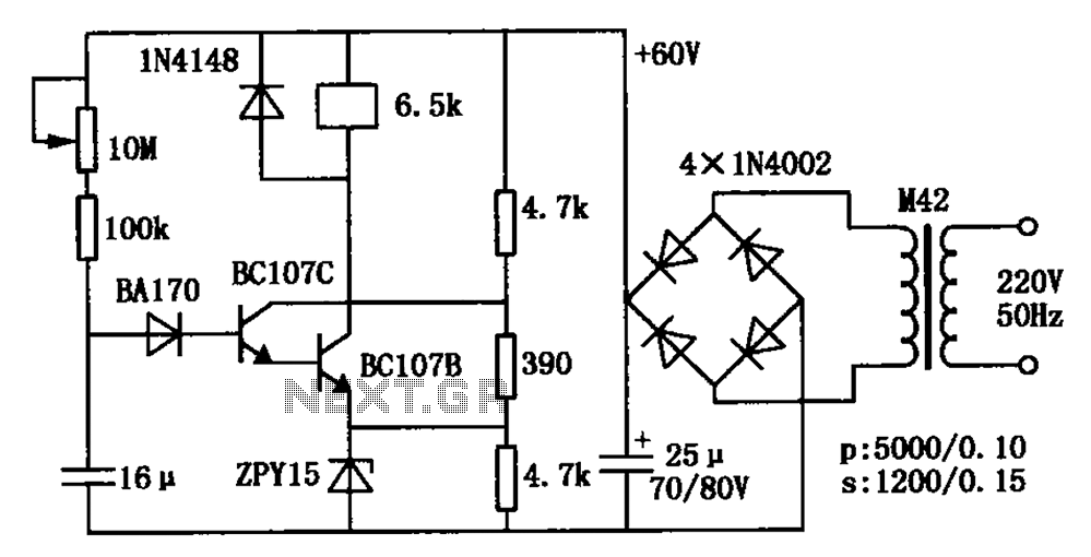
The circuit is a relay delay pull transistor configuration. Initially, when powered, the 16 µF capacitor has a voltage of zero, resulting in both transistors being off, and the relay remains inactive. As the 16 µF capacitor charges over...
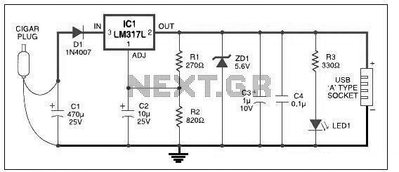
This USB car charger circuit adapter is designed for use with a car's cigarette lighter socket. It functions as a DC-DC power converter, effectively converting the 12V voltage from the car battery into a stable 5V output. This circuit...