
COLPITTS 1 To 20 MHz Crystal Oscillator
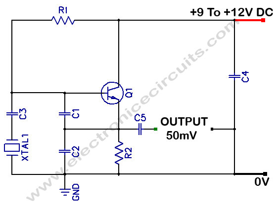
The Colpitts oscillator is a type of electronic oscillator that uses a combination of capacitors and an inductor to produce oscillations. In this particular circuit, the oscillator is configured to operate within the frequency range of 1 MHz to 20 MHz, making it suitable for various applications including signal generation and frequency modulation.
The core components of the Colpitts oscillator include a transistor, which acts as the active amplifying element, and a tank circuit comprising an inductor and two capacitors. The values of these components determine the oscillation frequency. The tank circuit is crucial as it sets up the resonant frequency, which can be calculated using the formula:
\[ f = \frac{1}{2\pi\sqrt{LC}} \]
where \( f \) is the frequency, \( L \) is the inductance in henries, and \( C \) is the total capacitance in farads. The capacitors are typically arranged in series and parallel configurations to achieve the desired capacitance value.
The circuit may also include additional components such as resistors for biasing the transistor and ensuring stable operation, as well as a power supply to provide the necessary voltage to the circuit. It is important to select components that can handle the frequency range specified, ensuring minimal phase noise and distortion during oscillation.
In practical applications, the output of the Colpitts oscillator can be used to drive other circuits, serve as a clock signal for digital systems, or be modulated for communication purposes. The design is favored for its simplicity and effectiveness in generating stable frequencies over a wide range. Proper layout and shielding techniques should be employed to minimize interference and maintain signal integrity in high-frequency operations.Colpitts 1MHz To 20 MHz Crystal Oscillator Circuit This is a simple Colpitts crystal oscillator for 1 to 20 MHz, PARTS.. 🔗 External reference
Related Circuits
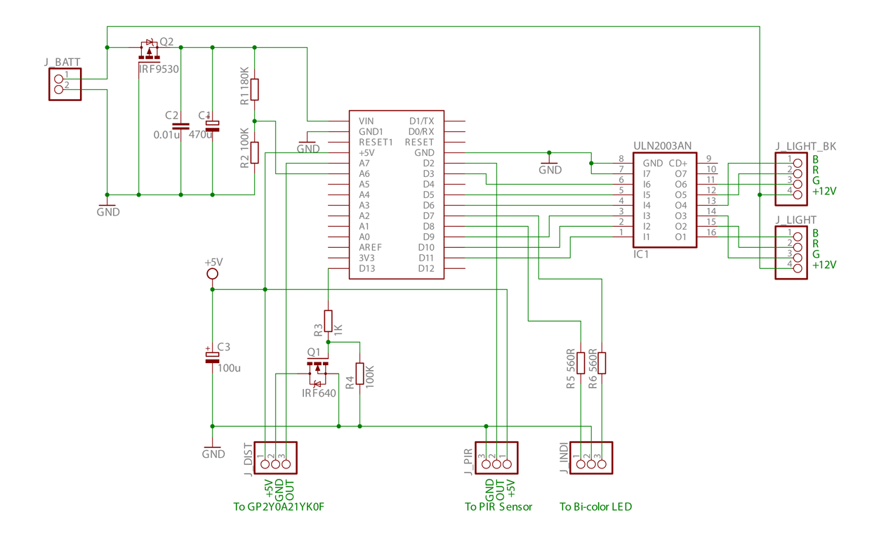
This is the initial phase of an Arduino-controlled PWM RGB LED project, which incorporates distance and PIR sensor control along with a sleep mode feature. The project utilizes an Arduino microcontroller to manage a Pulse Width Modulation (PWM) RGB LED,...
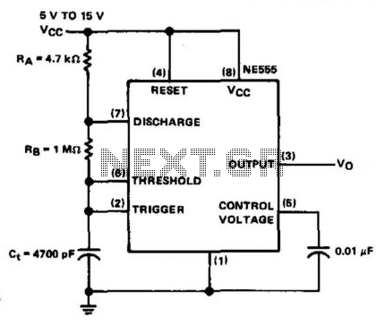
The NE555 timer is configured in astable mode and utilizes three timing components (RA, RB, and Ct). A 0.01 µF bypass capacitor is connected to pin 5 to enhance noise immunity. The operational limitations of the astable mode are...
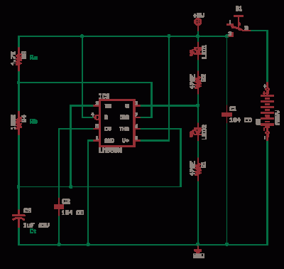
The LM311 is a comparator that operates from a single 5V supply or dual supplies, with an input current of 150 nA and an output drive capability of 50 V and 50 mA. It features a TTL-CMOS compatible output....
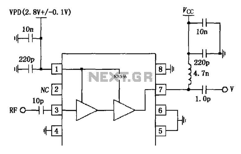
The circuit is constituted by the RF2324 1880MHz internal amplifier collector bias application. A radio frequency (RF) signal enters through input pin 3 and is processed by a preamplifier. The final stage power amplifier output is amplified by 7...
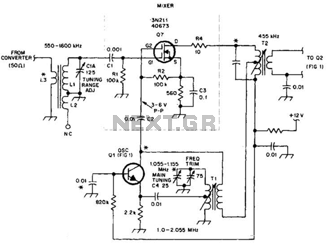
This circuit is an enhanced front end for upgrading a transistor AM receiver. This front end is beneficial when the radio is intended to function as a tunable IF amplifier with shortwave converters. The circuit described serves as a sophisticated...
The P-C70-A from Antique Electronics Supply performs effectively, potentially even better than coils that can be wound manually. While winding coils can be an engaging experiment, an alternative circuit is available for those who prefer to bypass the winding...
Warning: include(partials/cookie-banner.php): Failed to open stream: Permission denied in /var/www/html/nextgr/view-circuit.php on line 713
Warning: include(): Failed opening 'partials/cookie-banner.php' for inclusion (include_path='.:/usr/share/php') in /var/www/html/nextgr/view-circuit.php on line 713