
Square wave oscillator
The generator circuit produces interrupted square pulses, with vibrations occurring at various points in the circuit when switch S1 is in the ON position at location 3, which corresponds to output Q3 of IC2/7. When a pulse line of approximately ± 5V is applied at input J1, it enters through switch S2 into the input of IC1A, which is a J-K flip-flop configured as a T flip-flop, ensuring that subsequent circuits produce pulses with a duration-to-period ratio of 50%. The frequency of the pulses is divided by 2, resulting in output pulses at Q-IC1A/1 that are submultiples of the original frequency. These pulses are then applied to the CLK input of IC2/14 and another input of IC3. IC2 functions as a decimal counter with decoded outputs. Each input pulse activates one of its outputs sequentially; the first pulse activates output Q1, the second activates Q2, and so forth, until the tenth pulse resets the counter, allowing the cycle to repeat with subsequent input pulses. The number of pulses that pass to the generator's output is determined by the counter, the flip-flop IC1B, and gate IC3. In this configuration, a logic high corresponds to +5V and a logic low corresponds to -5V. The position of switch S1 determines how many pulses are outputted by the generator. In the final position of S1 (position 10), flip-flop IC1B does not perform a reset, allowing continuous pulses to be presented at the generator's output.
The output stage of the generator provides three different voltage levels: the positive voltage is created by the saturation of Q2 and cutoff of Q3, the null level results from the cutoff of both transistors, and the negative voltage is controlled by Q2 in cutoff and Q3 in saturation. The signal is outputted at J2 via potentiometer RV1, which, along with resistor R8, provides an output impedance of 600 ohms. The circuit can convert sine wave, triangular, and other signals into square pulses using the gates IC3B-C-D. The selection of direct or transformed incoming signals is managed by switch S2. Switch S1 can also be replaced by a high-quality 10-position rotary switch. The circuit is powered by two NiCd batteries, but it can also be powered by a suitable power supply. Voltage stabilization is achieved using two zener diodes.
Part List
R1-10= 10Kohm RV1= 1.2Kohm linear pot. IC1= 4027
R2= 47Kohm C1= 15pF ceramic IC2= 4027
R3= 22Kohm C2-3= 10nF 63V MKT IC3= 4001B
R4-5= 18Kohm C4-5= 470uF 16V S1= switch DIL 10S
R6-7= 4.7Kohm C6= 1uF 63V MKT S2-3= 2X2 mini switch
R8= 1.2Kohm D1-2= 5.1V 0.5W zener LD1= LED
R10= 100Kohm D3-4= 1N4148 BATT= 9V Battery NiCd
R11-13= 470 ohm Q1-2= BC560C
R12= 1.5Kohm Q3= BC550CThe generators of square pulses, are used in a lot of applications, between which the adjustment of conditions of entry in the digital circuits and the control of amplifiers acoustic frequencies. This circuit is a generator that it produces, in combination with a other generator, sine wave frequencies or square pulses, continuous or interrupted square pulses.
Main characteristic the generator it is, that the circle of operation can be regulated so as to he is constituted from until ten interrupted pulse. This pulses are particularly useful for the adjust amplifiers, loudspeaker, rooms of hearings etc. A other qualification of generator are that her pulses have level of report the 0V, without it is used for aim, capacitor in the exit. The absence of capacitor in the exit, has as result the production of clearly square pulses in any frequency of operation.
The generator work without perceptible distortion up to their 100KHZ.Her pulses have width 5Vpp (± 2.5V) and cover the needs of all amplifiers acoustic frequencies. In the cases where we needed signal of smaller width, then we can him decrease with the pontesometer RV1.
The generator is supplied with ± 5V, provided from two batteries or from one suitable power supply. Placing the S1, in different places from the 1 until 10, (a place each time), the crowd of output pulses, in each circle of operation can be altered from 1 until 10 and the duration of pause, (when the signal is maintained in the level of 0V), from 9 until 0. The waveform [1] -acquaintance as burst - it is particularly benefit for the control of instability low or high frequency circuits.
How it works? The circuit of generator that produces the interrupted square pulses and the produced vibrations in various points of circuit, when the selector of switch S1 is (ON), in the place 3, that correspond in exit Q3 of IC2/7. If in entry J1 we apply pulse line, width ± 5V, then these via the S2, enter in the entry of 3 IC1A that is j-k flip-flop as T, with a view to it ensures in the circuits that follow, pulses with reason of duration to period 50%.
Become division of frequency pulses, via 2. Thus in the exit Q-IC1A/1, are presented pulses with submultiples frequency. This pulses are applied in entry CLK, the IC2/14 and in a entry of IC3?. The IC2 is one decimal counter with decode exits. Each pulse of entry makes [ H ], one from his exits and concretely the one that corresponds in the content of enumeration. In the first pulse of entry, [ H ] becomes only exit Q1, of counter, while all the other are maintained in [ L].
The second pulse of entry makes [ H ], the exit Q2, third the Q3. The tenth pulse annihilates the content counter and it makes [ H ] the exit Qo, in order to is repeated the same circle of operation for the next pulses, entering pulse line. The number of pulses that will pass to the exit of generator is checked from counter, the flip-flop IC1B, and gate IC3?.
In the particular application the logic [ H ] corresponds in + 5V and the logic [ 0 ] from the -5v. Proportionally the place that will be placed switch S1, is checked the number of pulses that will pass to the exit of generator. In the last place of S1 (place 10), flip-flop IC1B does not make RESET, so that are presented pulses continuity in the exit of generator.
In the last place of S1 (place 10), flip-flop IC1B does not make RESET, so that are presented pulses continuity in the exit of generator. The output stage of generator, gives the three different levels of level that we needed: the output positive voltage it is created by the drive of Q2, in the satiation and Q3 in the cutting off, null from the cutoff of also two transistors and negative from the control of Q2 in the cutoff and Q3 in the satiation.
The signal is applied in exit J2 via the pontesometer RV1, that with the R8, gives output impedance 600R. Can we change sine wave, triangular etc, signals in square pulses with the circuit of entry, that is constituted by the gates IC3B-C-D.
The choice direct or transformation, the entering signals, becomes from switch S2. Switch S1, can be also replaced from a switching switch of 10 places, good quality. The supply becomes from two batteries NiCd, but can become also from suitable power supply. The essential stabilisation of voltage, becomes from the two diodes zener. Part List R1-10= 10Kohm RV1= 1.2Kohm linear pot. IC1= 4027 R2= 47Kohm C1= 15pF ceramic IC2= 4027 R3= 22Kohm C2-3= 10nF 63V MKT IC3= 4001B R4-5= 18Kohm C4-5= 470uF 16V S1= switch DIL 10S R6-7= 4.7Kohm C6= 1uF 63V MKT S2-3= 2X2 mini switch R8= 1.2Kohm D1-2= 5.1V 0.5W zener LD1= LED R10= 100Kohm D3-4= 1N4148 BATT= 9V Battery NiCd R11-13= 470 ohm Q1-2= BC560C R12= 1.5Kohm Q3= BC550C 🔗 External reference
Related Circuits
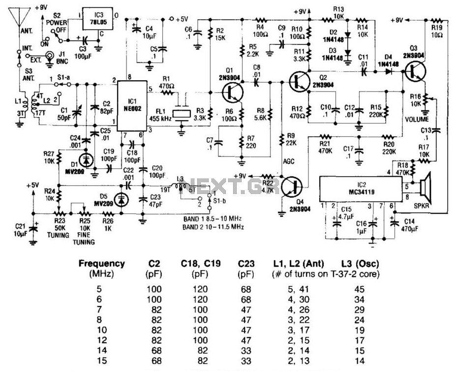
Using a Signetics NE602 in a varactor-tuned front end, the circuit of a shortwave receiver can be very simple and yet give high performance. This circuit also uses a ceramic filter as a sensitivity-determining device, two IF stages, AGC,...
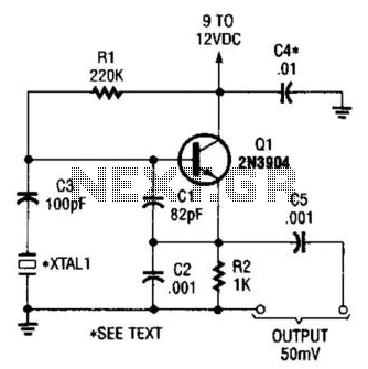
This is a simple Colpitts crystal oscillator for 1 to 20 MHz, which can be easily constructed from spare parts, provided that a crystal is available. The Colpitts oscillator is a type of electronic oscillator that utilizes a combination of...
Wien bridge oscillator. A phase-shift feedback oscillator that uses a Wien bridge as the basis for its operation. The Wien bridge oscillator is a type of electronic oscillator that generates sine waves. It operates based on the principle of phase...
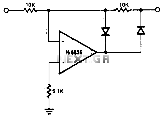
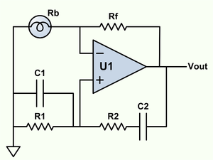
This circuit allows for precise half-wave rectification of the incoming signal. It exhibits a gain of 0 for positive signals and a gain of -1 for negative signals. By reversing the orientation of both diodes, the output polarity can...

This complex oscillator circuit utilizes a photocell and a common-mode suppression circuit to achieve a distortion level of 0.0003%. It replaces the lamp in the traditional Wien bridge with an electronic equivalent. The oscillator circuit described is a sophisticated design...
This circuit converts a sine wave into a square wave. It consists of a single 2-input NAND Schmitt trigger configured as an inverter, with a trigger level adjustment at its input. As the input voltage exceeds the gate's trigger...