
Wien bridge sine wave oscillator circuit composed of LM101A
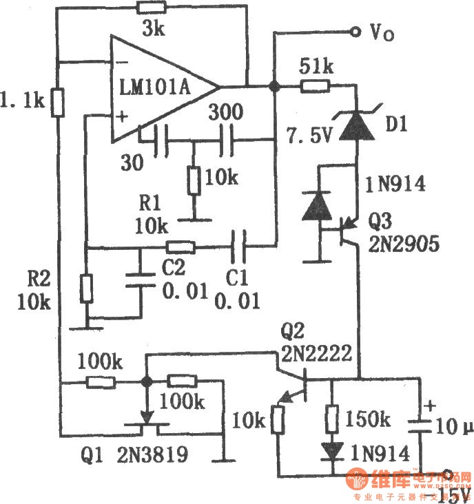
The Wien bridge oscillator is a well-known electronic circuit utilized for generating sine waves. It employs a combination of resistors and capacitors to create a feedback loop that allows for sustained oscillations. The circuit operates on the principle of balancing the gain and feedback to achieve a stable oscillation frequency.
In this configuration, the FET plays a crucial role in controlling the negative feedback. Its internal resistance varies with the gate voltage, which is influenced by the output voltage of the oscillator. When the output amplitude exceeds a specific threshold, the feedback mechanism activates the transistor Q2, which subsequently alters the gate voltage of Q1, effectively regulating the output amplitude. This automatic gain control feature is essential for maintaining the oscillator's stability and preventing distortion.
The positive feedback loop, formed by components C1, C2, R1, and R2, is critical for initiating and sustaining oscillations. The values of these components must be carefully selected to ensure that the phase shift around the loop is precisely 360 degrees, which is necessary for oscillation. The calculated oscillation frequency of approximately 1.6 kHz indicates that this circuit is suitable for applications requiring low-frequency sine wave generation.
In practical implementations, the addition of a 100kΩ resistor between the drain and gate or gate and source of the FET is significant. This resistor helps to maintain the FET's operation within its linear region, thereby minimizing harmonic distortion and ensuring a cleaner output waveform. The overall design of the Wien bridge oscillator makes it a versatile choice for audio signal generation, testing, and other applications where stable sine wave outputs are required.The chart shows the Wien bridge sine wave oscillator circuit. The amount of negative feedback circuit is determined by the internal resistance of FET. When the peak value of oscillator output reaches the regulated voltage of regulator diode D1, Q2 turns on, then the grid of Q1 FET becomes negative, Q1`s drain - source resistance increases, the neg ative feedback increases, loop gain decreases. Similarly, when the oscillation amplitude decreases, the loop gain will increase, therefore, it can maintain a certain output range. C1, C2, R1 and R2 constitute a positive feedback loop to ensure the circuit oscillation. Connecting a l00k © resistor between drain and gate or gate and source of FET will ensure the FET working in the linear region and reducing distortion.
Circuit oscillation frequency: f0 = 1/2. According to the component value of the figure, the oscillation frequency R1C1 is calculated approximately 1. 6kHz. 🔗 External reference
Related Circuits
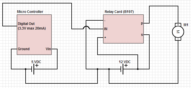
The objective is to control a 12 VDC device (on/off) from a microcontroller using a relay card. The relay requires a 12 VDC operating power supply. To achieve the control of a 12 VDC device using a microcontroller and a...
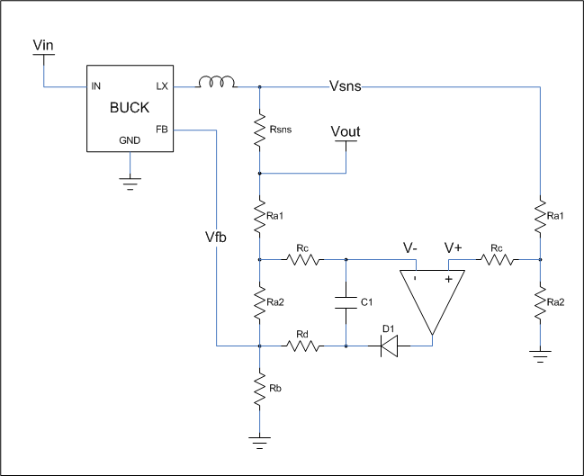
This is a cost-effective circuit that incorporates precise current limiting functionality into a voltage regulator. The circuit described is designed to enhance the performance of a voltage regulator by integrating a current limiting feature. This is particularly beneficial in applications...
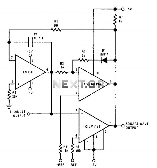
The positive and negative peak amplitudes can be controlled with an accuracy of approximately ±0.01 V through a DC input. Additionally, the output frequency and symmetry are easily adjustable. The oscillator is composed of an integrator and two comparators;...
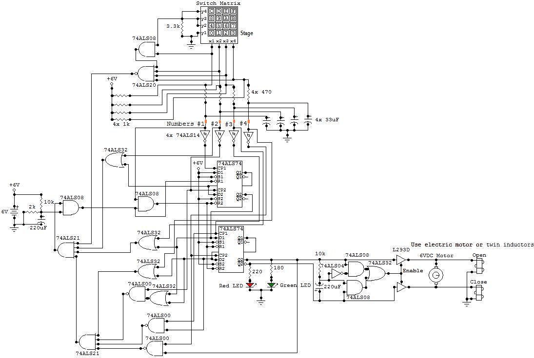
All the adapted numbers of the cipher are in the aforementioned line. To set the adjustment of the cardinal of the code, we accept to set the acceptable affiliation amid the bulge of the 7414 ascribe and the adapted...
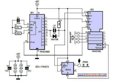
PWM waveforms are frequently utilized to regulate the speed of DC motors. The duty cycle of the digital waveform can be defined using an adjustable parameter. PWM (Pulse Width Modulation) is a technique employed to control the power delivered to...
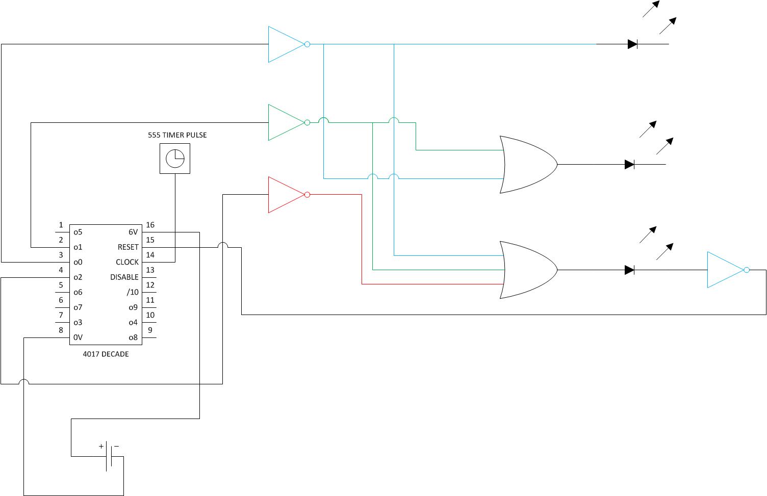
The goal is to create a timer activated by a button press, which will light three LEDs. After each 5-minute segment, one LED should turn off. After 15 minutes, a solenoid should ring a bell once. The individual has...
Warning: include(partials/cookie-banner.php): Failed to open stream: Permission denied in /var/www/html/nextgr/view-circuit.php on line 713
Warning: include(): Failed opening 'partials/cookie-banner.php' for inclusion (include_path='.:/usr/share/php') in /var/www/html/nextgr/view-circuit.php on line 713