
single-813 crystal oscillator transmitter

The single-813 crystal oscillator transmitter is a notable piece of vintage radio equipment, primarily used for amateur radio operations. This transmitter operates at a frequency determined by the crystal oscillator, which provides stability and precision in frequency output. The design incorporates an 813 vacuum tube, known for its high power handling capabilities, making it suitable for both CW and AM transmission modes.
The transmitter's output power ratings indicate its effectiveness in communication, with 150 watts available for CW operation, which is essential for long-distance communication, and 100 watts for AM telephony, allowing for voice transmission with modulated amplitude. The push-pull configuration utilized in the circuit enhances efficiency and linearity, reducing distortion in the transmitted signal, which is critical for maintaining audio quality in AM broadcasts.
Special attention must be paid to the screen voltage, which can significantly impact the performance and safety of the transmitter. Proper regulation and monitoring of this voltage are essential to prevent damage to the tubes and ensure reliable operation. The suggestion to explore alternative keying methods, such as cathode or grid-block keying, highlights the importance of safety in the design, as these methods can reduce the risk of arcing and improve the overall reliability of the transmitter during operation.
The historical significance of this transmitter is underscored by its inclusion in the RCA HamTips bulletin, a resource that provided valuable information and guidance to amateur radio operators of the time. The documented experiences of operators, such as Jack Meadows, W7QQQ, serve to illustrate the practical applications and performance of the single-813 transmitter in real-world conditions, further enhancing its legacy within the amateur radio community.Here is the single- 813 crystal oscillator transmitter, designed by RCA and exhibited in their advertisement on the back page of a "QST" magazine in 1938, and published by RCA in their HamTips bulletin, vol. 1, no. 4, dated December 1938. This transmitter`s output is 150 watts of CW or 100 watts of plate-modulated AM telephony. It seems obvious that this circuit and the 5 meter push-pull 807 oscillator transmitter were both designed by the same RCA team. The same caution about screen voltage applies here as well. In my opinion, the keying circuit leaves something to be desired. Perhaps cathode or grid-block keying should be tried. They would certainly be safer. Click here to view and/or print page 1 of the scanned copy of the RCA HamTips referenced above, which discusses this transmitter and its features, and click here for page 2.
And here are some photos of one of these built by Jack Meadows, W7QQQ, of Arizona. I have often heard this rig on the air on one or the other of the BA frequencies, 3547. 5 Khz. , and/or 7050 Khz, and have worked him when he was using it. It sounds very nice. 🔗 External reference
Related Circuits
This wireless headphone transmitter ensures a reliable connection over a distance of 2 meters. The oscillator frequency ranges between 1750 KHz and 3500 KHz, utilizing a ferrite bar as the antenna. IC1 amplifies the audio signal, while TC1 serves...

In this circuit, data at input C is amplified by IC2 and then fed to modulator IC1. IC1 generates two frequencies, depending on the values of C5, I10, R5, Rn, and R6. The frequency f1 is generated if pin...
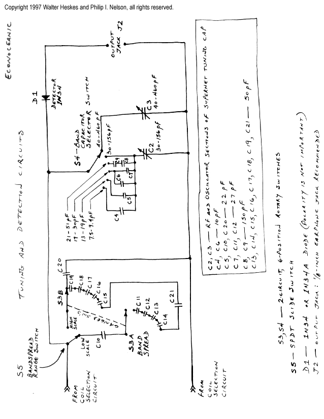
This project merges two significant themes from radio history: crystal radios and shortwave (SW) listening. It has been developed from the ground up by non-resident engineer Walter Heskes. Despite advancements in modern electronics, numerous crystal sets are actively used...

A practical project is being conducted using the LM741 operational amplifier configured as a Wien bridge oscillator. The component values are specified as follows: C1 = C2 = 0.01 µF, R1 = R2 = 3 kΩ, Rf = 2...
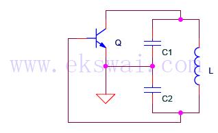
The Colpitts oscillator circuit is illustrated in Figure 1, with Q representing the transistor. The Colpitts and Hartley oscillator circuits are similar, differing primarily in the positions of the inductor and capacitor. An equivalent circuit of the oscillator is...

Construct a low-power FM transmitter using surface-mount devices (SMD) that can be received by a standard FM radio. The proposed low-power FM transmitter circuit utilizes surface-mount devices (SMD) to achieve compactness and efficiency. The primary components of the circuit include...