
colpitts oscillator

The Colpitts Oscillator is a type of electronic oscillator that utilizes a combination of an inductor (L) and two capacitors (C1 and C2) to produce an oscillating signal. The configuration typically involves an NPN transistor, which serves as the active device to amplify the signal. The feedback network, composed of capacitors C1 and C2, is critical for determining the oscillation frequency and stability of the circuit.
In this circuit, the capacitors C1 and C2 are connected in series, and their combined capacitance (CT) is calculated using the formula CT = (C1*C2)/(C1+C2). This relationship affects the overall feedback ratio, which is essential for sustaining oscillations. The inductor L is also a key component, as it, along with CT, defines the oscillation frequency through the equation f = 1/(2*pi*sqrt(L*CT)).
The design of the Colpitts Oscillator allows for the generation of sine wave signals, making it suitable for various applications, including signal generation and frequency synthesis. The choice of component values directly influences the performance characteristics, such as frequency stability, output amplitude, and phase noise. Proper simulation in environments like SimElectronics aids in optimizing these parameters before physical implementation.Simulation of Colpitts Oscillator circuit using npn transistor and other components available in SimElectronics is shown. The feedback ratio is determined by the relative values of the Capacitors C1 and C2. Frequency of oscillation is given by f = 1/(2*pi*sqrt(L*CT) where CT = (C1*C2)/(C1+C2) 🔗 External reference
Related Circuits
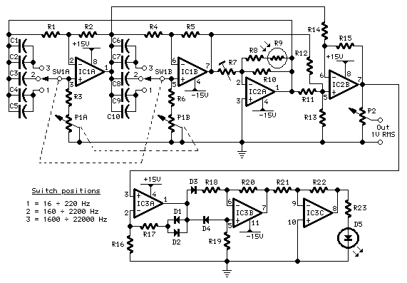
This oscillator generates low-distortion sine waves within a frequency range of 16 to 22,000 Hz. The sine wave oscillator is designed to produce high-quality sine wave outputs with minimal distortion across a wide frequency spectrum. The operational range of 16...
The circuit depicted in this schematic diagram is a square-wave oscillator circuit. The primary component of this oscillator circuit is the LP165/365 comparator. The square-wave oscillator circuit utilizes the LP165/365 comparator to generate a continuous square wave output. The...
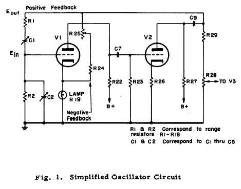
After repairing several Hewlett Packard vacuum tube voltmeters, research was conducted on the company's history. An HP-200C oscillator was located, which closely resembles the company's initial product. It is a Wien bridge resistance-tuned oscillator featuring a light bulb stabilized...
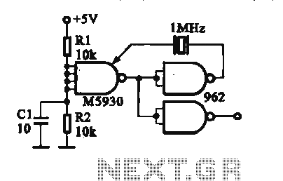
A crystal oscillator is implemented using a DTL (Diode-Transistor Logic) integrated circuit. The oscillation frequencies are 100 kHz and 1 MHz. The circuit consists of a gate circuit that generates a signal for the oscillator circuitry in DTL. The crystal...
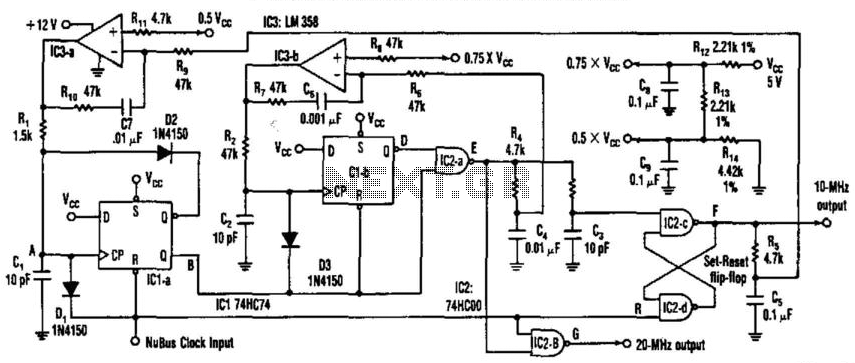
This circuit generates a 20-MHz clock signal that is phase locked to a 10-MHz clock found in the Apple MAC II. To create the 20-MHz output, the circuit generates a 25 ns negative-going pulse that is delayed by 50...
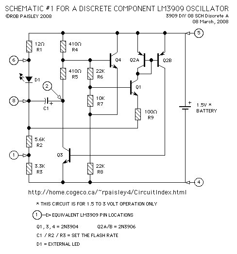
This page features a replacement circuit for the LM3909 LED Flasher / Oscillator using discrete components. The circuit is functionally the same as the integrated LM3909 but has a minor variation of the components used. Naturally the circuit will...