
Colpitts Oscillator Calculator

The Colpitts oscillator is a type of electronic oscillator that generates sinusoidal waveforms through the use of a transistor and a combination of capacitors and inductors. The configuration is distinguished by its ability to provide stable oscillations at high frequencies, making it suitable for applications in RF (radio frequency) communication and signal generation.
In this circuit, the transistor Q acts as an amplifier, providing the necessary gain for the oscillator to function. The capacitors C1 and C2, along with the inductor L, form a resonant tank circuit that determines the frequency of oscillation. The feedback network is crucial for sustaining oscillations; it ensures that a portion of the output signal is fed back to the input in phase with the original signal. This phase alignment is essential for maintaining continuous oscillation.
The formula for the resonant frequency (f) of the Colpitts oscillator can be expressed as:
\[
f = \frac{1}{2\pi\sqrt{L \cdot C_{eq}}}
\]
where \( C_{eq} \) is the equivalent capacitance of the capacitors C1 and C2, calculated using the formula for capacitors in series:
\[
\frac{1}{C_{eq}} = \frac{1}{C1} + \frac{1}{C2}
\]
The high Q value of the LC circuit is critical as it indicates low energy loss relative to the energy stored in the circuit, allowing for stable oscillations. The design must take into account the parasitic capacitances associated with the transistor, especially at higher frequencies, as these can significantly affect performance.
In high-frequency applications, the values of C1 and C2 are typically in the picofarad range, which minimizes their impact on the oscillation frequency while ensuring that the circuit can achieve the desired operational characteristics. The careful selection of components is necessary to optimize performance, particularly in achieving a clean oscillation waveform and maintaining frequency stability under varying load conditions.
Overall, the Colpitts oscillator circuit is a versatile and widely used design in electronic engineering, particularly in applications requiring precise frequency generation and signal processing.Colpitts oscillator circuit is shown in Figure 1, Q is the transistor. The Colpitts and Hartley oscillator circuit are similar, except the inductor, capacitor exchange of positions. Oscillator equivalent circuit shown in Figure 2. Capacitors C1, C2, and inductor L form a positive feedback network of selected frequency, feedback signals from both e
nds of capacitor C2, so called three-points capacitor oscillator circuit, also known as the feedback capacitor oscillator circuit. Feedback signal in phase with the input voltage to meet the oscillation of the phase equilibrium conditions, LC resonant circuit Q value is high enough under the conditions of the circuit`s oscillation frequency is approximately equal to the resonant frequency circuit.
Calculated as follows: Capacitance three-point oscillator circuit is characterized by a high oscillation frequency can do in general can reach more than 100MHz, because of the high harmonic impedance of C2 is small, the feedback voltage in the high harmonic components smaller, and thus oscillation waveform better. Also when the oscillation frequency is high, C1, C2`s value is very small, transistor-level capacitance will impact on the frequency.
🔗 External reference
Related Circuits
I am attempting to construct a Hartley oscillator using a bypassed common emitter configuration. The goal is to achieve oscillation at a frequency of 200 kHz with a peak-to-peak voltage of 2 V, utilizing a BC547B transistor. The Hartley oscillator...
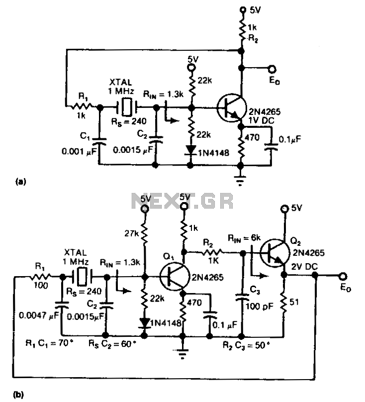
The circuit is an inverter configured as a linear amplifier. By incorporating a crystal and capacitors into the feedback path, the amplifier is transformed into an oscillator, enabling it to oscillate at or near the crystal's resonant frequency. Trimmer...
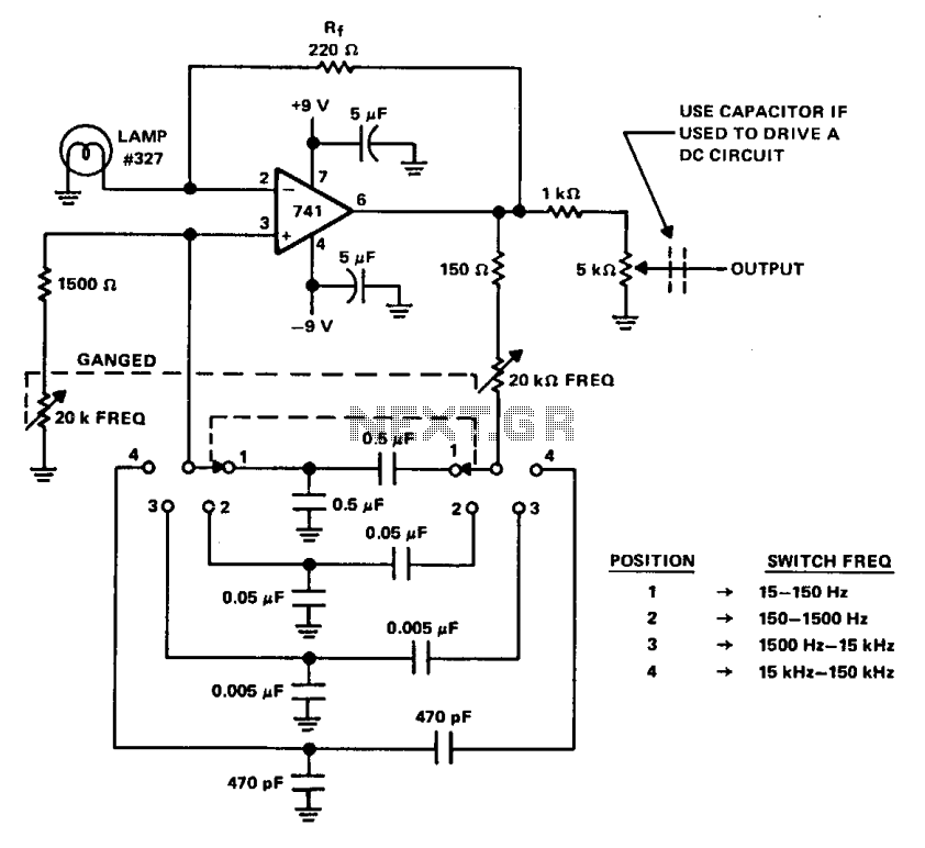
A Wien bridge oscillator generates sine waves with a very low distortion level. It produces zero phase shift at a single frequency (f = Vx t RC), which is the oscillation frequency. Stable oscillation can only occur if the...
The oscillator was designed to utilize resistors and capacitors instead of large low-frequency LC tank circuits for generating audio frequencies. It achieved low distortion (less than 0.5%) by employing a two-stage amplifier with sufficient negative feedback to set the...

This circuit includes an amplifier designed to deliver +10 dBm to an SBL series (Mini-Circuits) or a similar type of doubly-balanced mixer assembly. The circuit parameters are specified for 80 to 90 MHz crystals, although the values of the...
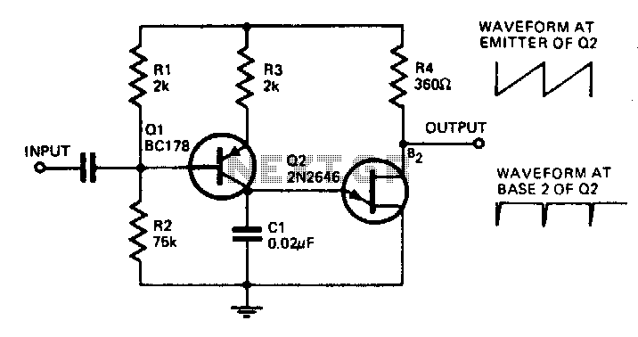
With the component values shown, the oscillator has a frequency of 8 kHz. When an input signal is applied to the base of Q1, the current flowing through Q1 is varied, thus affecting the time required to charge C1....