
Comb electric circuit
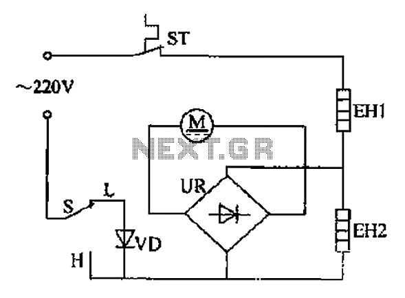
The comb electric circuit operates by utilizing a dual-temperature control system, allowing users to select between low (L) and high (H) temperature profiles via switch S. This functionality is critical for accommodating various hair types and styling needs. When the switch is engaged, current flows through the heating elements, EH1 or EH2, which are strategically positioned to efficiently transfer heat to the hair.
The circuit employs a rectifier to convert the incoming 220V AC supply into a stable DC output. This rectification is essential for powering the small DC motor M, which drives the mechanical components of the comb. The motor's rotation is synchronized with the heating elements, ensuring that heat is applied consistently during the styling process.
The heating wires are designed to reach the desired temperature quickly, thanks to their low thermal mass and high conductivity. The circuit may also include thermal protection features to prevent overheating, ensuring safety during operation. Additionally, an LED indicator may be incorporated to signal when the device is powered on and heating.
Overall, this comb electric circuit exemplifies a practical application of electronics in personal grooming devices, combining heating and mechanical motion to facilitate effective hair styling. Comb electric circuit shown in Figure 1-3. It has two temperature options, switch S into L or H profile file, you can get different temperatures. Then later on switch S, the ci rcuit is turned on, the heating wire EH1 or EH2 heating, after UR rectification, the 220v alternating current into direct current, so that a small DC motor M is rotated. Heat into the hair, to shaping hair.
Related Circuits
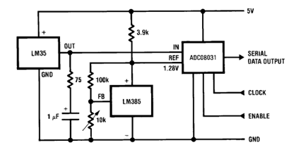
The circuit illustrates a Temperature to Digital Converter diagram utilizing the LM35 sensor, which includes a beneficial bypass capacitor connected from VIN to ground and a series RC damper. The described circuit employs the LM35 temperature sensor, a precision integrated...
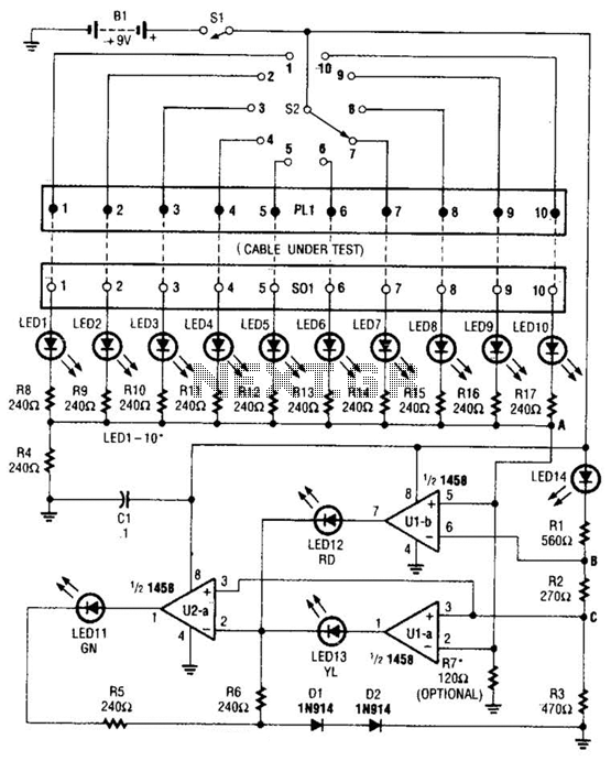
The cable tester utilizes two operational amplifiers (op-amps) configured as window comparators to detect short or open circuit conditions. A third op-amp comparator is employed to indicate a properly functioning circuit, meaning it is neither open nor shorted. Colored...
The thermistor utilized has a resistance of 15k ohms at 25 degrees Celsius and 45k ohms at 0 degrees Celsius. A suitable bead-type thermistor can be sourced from the Maplin catalogue. The inclusion of a 100k potentiometer enables this...
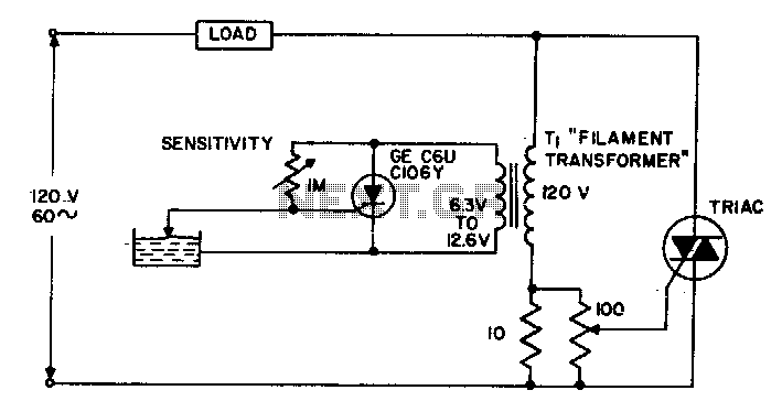
The circuit supplies power to the load until water conducts through the probe, allowing gate current to bypass from the low current SCR. This configuration provides an isolated low voltage probe to meet safety requirements. The described circuit operates as...
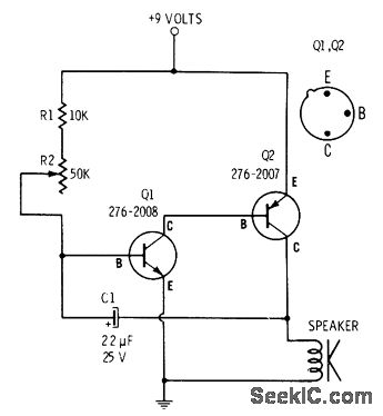
R2 controls the charging speed of capacitor C1. At a specific charge level, C1 triggers transistors Q1 and Q2, which release a 9-volt pulse. This pulse generates a clicking sound. The discharge process of the capacitor involves it charging...
All electronic circuits were initially built on breadboards. Once the circuits were operational, they were soldered onto perfboards to create a more durable system. A power board was designed to stack two batteries in series, providing access to a...
Warning: include(partials/cookie-banner.php): Failed to open stream: Permission denied in /var/www/html/nextgr/view-circuit.php on line 713
Warning: include(): Failed opening 'partials/cookie-banner.php' for inclusion (include_path='.:/usr/share/php') in /var/www/html/nextgr/view-circuit.php on line 713