
Cable Tester Circuit
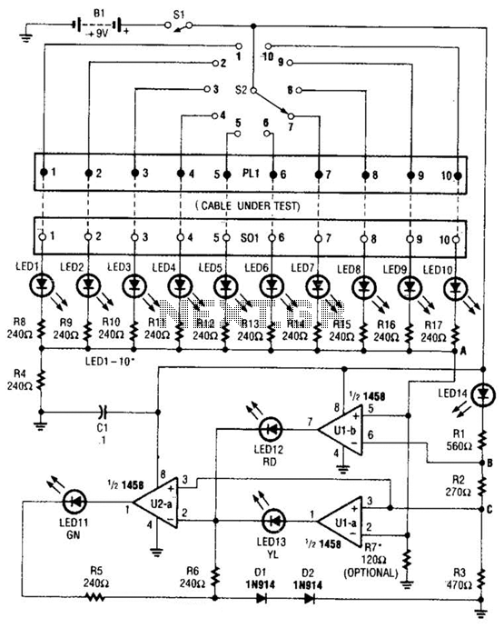
The cable tester circuit is designed for efficient and reliable testing of cable integrity. The two op-amps configured as window comparators are set up to monitor the voltage levels across the cable conductors. When a short circuit occurs, the voltage level drops below a predefined threshold, triggering the red LED to illuminate, signaling the presence of a fault. Conversely, if an open circuit is detected, the voltage remains above the threshold, and the yellow LED is activated to indicate an open conductor.
The third op-amp comparator plays a crucial role in verifying the integrity of the circuit. It ensures that when all conductors are intact, the green LED lights up, providing a clear visual indication that the cable is functioning as intended.
The inclusion of a bar-graph display enhances the usability of the tester by allowing for real-time monitoring of each conductor's status. Each LED in the bar-graph corresponds to a specific conductor, illuminating sequentially as the tester cycles through the conductors. This feature not only facilitates quick identification of faults but also provides a comprehensive overview of the cable's condition.
Overall, the design of this cable tester emphasizes clarity and functionality, utilizing simple yet effective components to deliver accurate testing results. The use of color-coded LEDs and a bar-graph display ensures that users can easily interpret the status of the cable under test, making it an invaluable tool for technicians and engineers in the field of electronics. At the heart of the cable tester are two op amps, which are used as a window- comparator to indicate a short- or open-circuit condition. A third op-amp comparator is used to indicate a good circuit (i.e., neither open nor shorted). Colored LEDs are used to show the condition of individual conductors within the cable under test; a red one to indicate a short between conductors, a yellow one to identify an open conductor, and a green one to signify that the conductor is okay.
Individual LEDs of a bar-graph display are used to show which conductor in the cable is being tested. 🔗 External reference
Related Circuits

Electronic schematics collections provide a platform for discussions related to electronic circuit schematics, printed circuit board (PCB) diagrams, and various electronics projects. These collections serve as valuable resources for engineers, students, and hobbyists interested in electronics design and development. They...
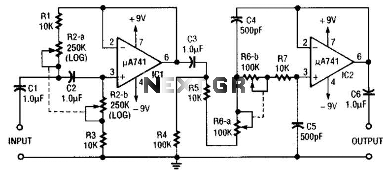
This circuit is a variable audio bandpass filter that features a low cutoff adjustable from approximately 25 Hz to 700 Hz and a high cutoff adjustable from 2.5 kHz to over 20 kHz. The roll-off is set at 12...
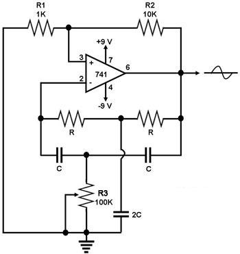
This circuit generates a sine wave using a single operational amplifier (741). The feedback loop of the op-amp includes a twin-T filter connected between its output and inverting input. Positive feedback for oscillation is provided by resistor R2. The...
Are you unfamiliar with the basics of electronics? An online store has recently opened, offering four excellent books on basic electronics for sale. Reviews of these books are available, and purchases can be made as desired. These books are...
This circuit diagram illustrates the conversion of a speaker into a microphone. When sound waves impact the diaphragm of a speaker, fluctuations occur in the coil, generating an induced voltage. This induced voltage is typically substantial but low in...
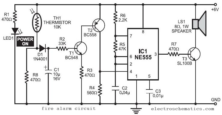
In this fire alarm circuit project, a thermistor functions as the heat sensor. When the temperature rises, its resistance decreases, and conversely, when the temperature falls, its resistance increases. Under normal conditions... In this fire alarm circuit, the thermistor is...
Warning: include(partials/cookie-banner.php): Failed to open stream: Permission denied in /var/www/html/nextgr/view-circuit.php on line 713
Warning: include(): Failed opening 'partials/cookie-banner.php' for inclusion (include_path='.:/usr/share/php') in /var/www/html/nextgr/view-circuit.php on line 713