
Combinational Conjuring Trick
The described circuit operates on a principle of color-coded logic, where each switch is assigned to a specific lightbulb based on the color of its cover. The circuit comprises three switches labeled S19, S20, and S21, which are each equipped with a distinctively colored cover—let's say red, blue, and green. These switches control three corresponding lightbulbs, LP1, LP2, and LP3, which are also colored red, blue, and green.
The intriguing aspect of this circuit lies in its design, which allows for the interchangeability of both the switch covers and the lightbulbs without altering their inherent functionality. Regardless of how the components are rearranged, the operational logic remains intact; a switch with a red cover will always control the red lightbulb, irrespective of the physical arrangement of the components. This creates an illusion that can be perceived as a conjuring trick, as the outcome remains consistent even when the variables are manipulated.
In terms of electronic design, the switches can be simple SPST (Single Pole Single Throw) types, where the closed position completes the circuit for the respective lightbulb. The lightbulbs can be standard incandescent or LED types, depending on the desired brightness and power consumption. The circuit can be powered by a standard AC or DC source, depending on the specifications of the lightbulbs used.
To enhance the circuit's reliability, it is advisable to include resistors in series with the lightbulbs if using LEDs, to limit the current and prevent damage. Additionally, a fuse could be added for overcurrent protection, ensuring the safety of the entire assembly. The overall layout should be designed to minimize the risk of accidental short circuits, especially considering the physical manipulation of the components during the performance of the trick.
This circuit can serve as an excellent educational tool to demonstrate fundamental principles of electronics, such as circuit completion, switch operation, and the effects of color coding in logical systems.The simple circuit of Fig.1 emulates a similar conjuring trick which sells for hundreds of Pounds. The trick seems to do the almost-impossible from an electronic point of view, let alone from the point of view of common sense. It consists of a bank of three on-off switches (S19-S21), which have three switch covers, each of a different colour.
These switch a bank of three lightbulbs (LP1-LP3), each of a different colour. The colours of the lightbulbs correspond with the colours of the switch covers. Now comes the interesting part. The switch covers may be exchanged at will, but still they switch the lightbulbs of corresponding colour. Similarly, the lightbulbs may be exchanged at will, but still they respond to the switches of corresponding colour.
O 🔗 External reference
Related Circuits

The Cockcroft-Walton multiplier employs a series of diodes and capacitors arranged in a cascade to generate a high-voltage DC potential from an AC input. This circuit topology utilizes diodes to charge capacitors in parallel and discharge them in series....
Electronics tutorial on combinational logic circuits that utilize logic gates to create multiplexers, encoders, and solid-state switches. Combinational logic circuits are fundamental components in digital electronics, characterized by their ability to produce outputs based solely on the current inputs, without...

At the time, there was a desire to construct an ultimate continuity tester, leading to the creation of a wish list of required features. A genuine continuity tester is needed, as many multimeters and sounders react to resistances as...

This is a simple yet effective charger for lead-acid batteries. It utilizes a 12-volt car bulb as both a current regulator and a charge status indicator. The described circuit is an innovative approach to charging lead-acid batteries. It employs...
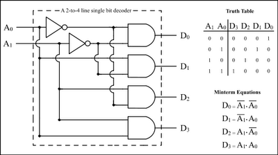
The Encoder and Decoder are different types of combinational circuits used to convert binary information to decimal, octal, and hexadecimal formats, and vice versa. A decoder is a combinational circuit that converts n-bit binary information into 2^n unique outputs....
Most of the ideas in this chapter can be found on the pages of this website, but just in case you want to go over the capabilities of the 508A, we have brought them together. Quite often when you...