
Commodore 64 Cassette Interface
The 6510 microprocessor (U7) is an 8-bit microprocessor that integrates a parallel I/O port, which includes pins P0 through P5. This I/O port is instrumental in interfacing with peripheral devices, particularly cassette players in this application. Pins P3 to P5 are dedicated to controlling the cassette interface circuitry, where P3 outputs the write data signal to the cassette connector CN3, specifically on pins E and 5.
Pin P4 serves as an input to monitor the status of the cassette deck's play switch, allowing the microprocessor to determine when playback is initiated. Pin P5 acts as an output that manages the operation of the cassette motor. The logic state of P5 is crucial; when it transitions to a low state, it triggers a sequence that involves transistor Q2 turning off. This action allows CR2 to regulate the voltage at the base of transistor Q1 to a steady 7.5 volts. As a result, Q1 and Q3 are forward biased, enabling current to flow through the cassette motor coil, thereby activating the motor.
In addition to the 6510, the circuit employs a Complex Interface Adapter (U1), which is responsible for managing data communication and control signals. The CIA features multiple parallel ports, serial outputs, and timers, facilitating a robust interface between the microprocessor and external devices. The read data from the cassette enters the circuit through pins D4 of connector CN3. The CIA processes this data and accepts the read signal through the FLAG input pin (pin 24), allowing for efficient data handling and control operations within the system. This architecture illustrates a well-integrated design that effectively combines microprocessor capabilities with peripheral control for cassette operations.U7 is a 6510 microprocessor. One of the features of the 6510 is a built in parallel I/O port (P0-P5). P3 - P5 control most of the cassette interface circuitry. P3 pin p6 of U7 outputs the write data signal to connector CN3 on pins E and 5. P4 is an input that senses the play switch depressed on the cassette deck. P5 is on output that controls thecassette motor. When P5 goes "low", Q2 cuts off, CR2 regulates Vb of Q1 at 7. 5 volts, this forward biases Q1 and Q3, passing current through the cassette motor coil. U1 is a Complex Interface Adapter (CIA). Parallel ports, serial outputs, and Timers are standard features of the CIA. Read data enters on pins D, 4 of CN3. U1 accepts the read data signal on the FLAG input pin 24. 🔗 External reference
Related Circuits
This is an interface circuit for digital data input. The circuit consists of a touch button, an operational amplifier (op-amp), a diode, a capacitor, and resistors. Any conductive surface can be used. The interface circuit designed for digital data input...
If you have access to a Lowe HF-225 shortwave receiver, then you might be interested in this page. If you don't, then you'd probably be better off leaving now. What follows is a project I completed some time ago,...
Build an interface board to connect scientific equipment, specifically a pair of photovoltaic tubes, to a personal computer for acquiring measurement results. The signal properties include two channels with a common ground, a one-second acquisition time, and a maximum...
The USB charger power supply is designed for use in MP3 and MP4 chargers. It accepts an input of AC 160-240V at 50/60Hz and has a rated output of DC 5V at 250mA. For applications requiring a long-term higher...
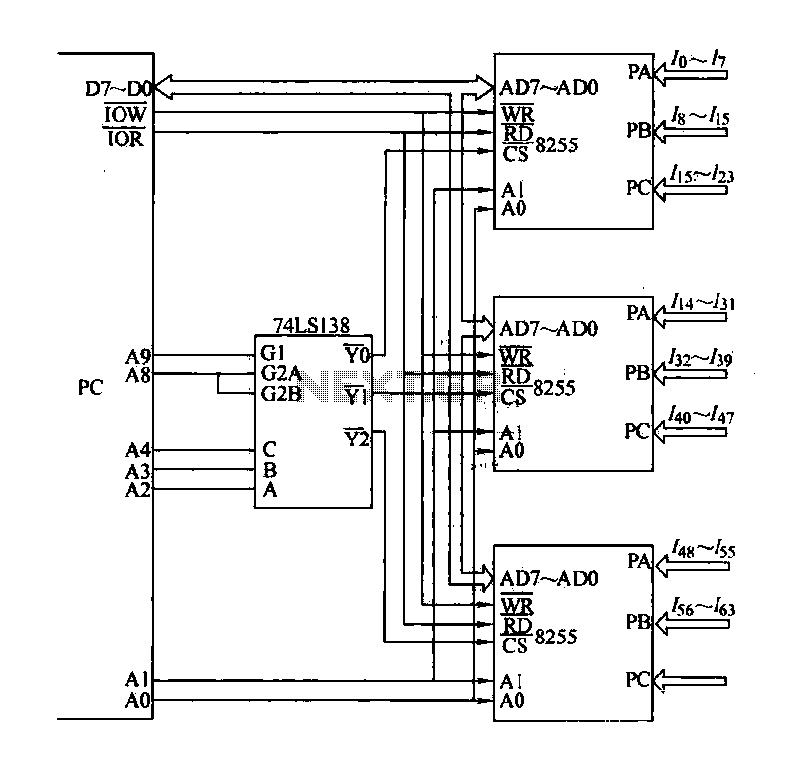
The computer control system is designed to detect signal path switching, requiring multiple input interface expansions. This system can switch all signal inputs into the computer. By utilizing a programmable chip, the 8255 expansion input interface allows for three...
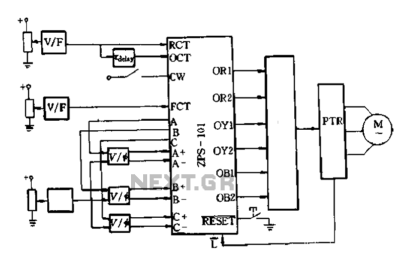
An AC-DC-AC circuit utilizes a power transistor as a switching device with analog control, as recommended in the wiring diagram of Figure 6-10. This circuit generates a voltage-controlled oscillator (VCO) using OCT and FCT, with RCT available for OCT...