
Commodore 64 Keyboard Joystick & Paddle Interfaces
The circuit described involves a Complex Interface Adapter (CIA), designated as U1, which plays a critical role in interfacing the keyboard and joystick inputs with the main processing unit. The architecture includes two parallel ports: Port A, configured as outputs, and Port B, configured as inputs. The operational principle is based on a binary signaling system where a "0" bit is transmitted from Port A whenever a key is pressed. This bit is detected by Port B, facilitating the identification of keypress events.
The KERNAL ROM contains a dedicated program responsible for generating the output signals on Port A and interpreting the inputs from Port B. Upon pressing the restore key, a sequence is initiated that triggers a Non-Maskable Interrupt (NMI) via U20, affecting pin 6 of U9. This interrupt is essential for initializing the I/O interfaces, ensuring that the system is responsive to user inputs. Notably, if the STOP key is pressed concurrently, it initializes specific BASIC flags, indicating a dual-functionality in the interface design.
The joystick functionality is integrated into the system through the same CIA, where Port A handles inputs from the B joystick and Port B manages inputs from the A joystick. The design allows for directional movement and action inputs (fire button) to be detected through ground potential applications to the respective inputs of U1.
For the paddle controls, a variable resistor is employed, connected to a knob that adjusts resistance within an RC network. This configuration allows for dynamic control of the timing characteristics of the circuit, with the voltage across the capacitor being fed into an internal A/D converter of the SID chip (U18). The conversion process enables the digital representation of paddle position to be stored in SID registers, facilitating precise control in applications such as gaming.
The circuit also incorporates a 4066 CMOS switch (U28), which is responsible for routing signals from the paddles to the SID chip. The enabling mechanism relies on the state of inputs E0 to E3 of U28, which must be "high" for the signals to pass through. This design choice ensures that the paddle inputs are only processed when required, enhancing the efficiency and responsiveness of the system. Overall, the schematic effectively integrates keyboard and joystick functionalities, along with paddle controls, into a cohesive interface for user interaction.U1 is a Complex Interface Adapter (CIA). Both parallel ports are used to decode the keyswitches on the keyboard. Parallel port A signals (PA0 - PA7) are outputs. PArallel port B signals (PB0 - PB7) are inputs. A "0" bin is shifted through the parallel port A, when a key is depressed on the keyboard the "0" bit is returned on one of the parallel port B inputs. A program in the KERNAL ROM generates the shifting "0" bit output on parallel port A, and decodes the signals returning on the parallel port B inputs. Depressing the restore key causes U20 to trigger. U9 pin 6 goes "low" generating a Non- Maskable Interrupt (NMI) at the processor. This causes the processor to execute a subroutine which initializes the I/O interfaces. If the STOP key is depressed at the same time, BASIC flags are initialized. U1 also controls the joystick. Parallel port A accepts inputs from the B joystick connected to control port 2. Parallel port B accepts inputs from the A joystick connected to control port 1. When the joystick is moved up, down, left, right, or the fire button is depressed, a ground potential is applied to the appropriate input of U1.
A Variable resistor is connected to adjusting knob on the paddle. When the knob is rotated, the resistance varies controlling the time constant of an RC network. The Voltage developed across the capacitor is input to an A/D converter internal to the SID chip U18. The digital output is stored in one of the SID registers. The paddle position can be determined by the reading the contents of the appropriate register. U28 is a 4066 CMOS switch. The signals from the paddles are passed to the SID chip when the Enable inputs (E0 - E3) of U28 are "high".
🔗 External reference
Related Circuits
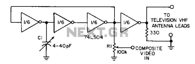
Three gates of a 74LS04 form the oscillator circuit. Capacitor C1 allows fine frequency adjustment to a specific television channel and helps stabilize the circuit. Potentiometer R1 acts as the mixing input and provides adjustment of the contrast ratio...
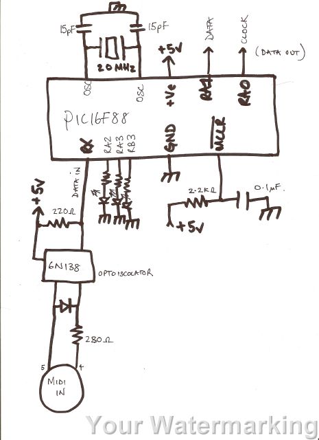
A code has been developed to process MIDI data received on the RX pin of the USART. It stores three bytes of data in a buffer, checks the first byte to determine if it is a MIDI "on" message...
With the phasing out of game, serial, and parallel ports from modern computers and the increasing popularity of USB, it is beneficial for hobbyists to learn how to work with USB. However, USB is a complex protocol that can...
This document details the AT Keyboard Interface and AT Keyboard Protocols. It includes an example of a Keyboard to ASCII decoder utilizing a 68HC705J1A microcontroller. The AT Keyboard Interface is a standard communication protocol used primarily in personal computers to...
Some games are easier to play with a digital joystick instead of an analogue type. Unfortunately, PC has only an analogue joystick connector, which makes it impossible to connect a normal digital joystick to it. But with a little...

This joystick model was introduced by IBM alongside their first IBM PC computer. It is a basic analog joystick featuring two buttons. The original joystick interface included a circuit for connecting two joysticks but only had one joystick connector....