
communication Multiplex data and LED pin
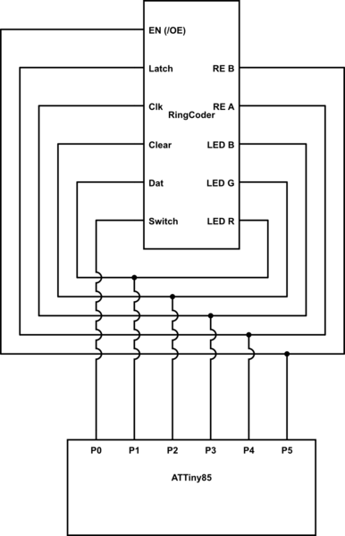
The circuit design will incorporate the ATtiny85 microcontroller, which features six general-purpose I/O pins, making it suitable for this application. The five pins dedicated to the shift registers will need to be configured to handle data, latch, and clock signals, while the sixth pin will be utilized for the RGB rotary encoder. A finite state machine will be implemented in the firmware to effectively manage the transitions between different operational states, allowing for efficient control of the RGB LEDs and the rotary encoder.
To accommodate the shared line for the RGB LEDs and the shift register signals, a multiplexing approach may be employed. This could involve using a transistor or a logic gate to switch between the RGB LED control and the shift register communication based on the current state of the FSM. The design must ensure that the timing of the signals is managed correctly to prevent conflicts between the shift register operations and the RGB LED control.
Furthermore, attention must be given to the pin assignments, especially regarding the shared /OE pin. It is advisable to reassign this pin to work with the switch instead of the rotary encoder to avoid any operational conflicts. This may require a redesign of the encoder interface to ensure that it can still function correctly without interfering with the essential operations of the shift registers.
Overall, the circuit schematic will depict the ATtiny85, the shift registers, the RGB LEDs, and the rotary encoder, along with any necessary components such as resistors, capacitors, and transistors to facilitate proper operation and signal integrity. The design will be optimized for space and efficiency, taking full advantage of the capabilities of the ATtiny85 while maintaining functionality equivalent to that of the Arduino UNO implementation.Performing a chip conversion for the Sparkfun LED RingCoder. The sample code provided with the product works well on an Arduino UNO, but it uses a pin for each I/O - 5 pins for the shift registers and 6 pins for the RGB rotary encoder. What I want to do is use a 6 I/O Tiny85 instead of a full-blown UNO. So I would like to re-use 5of the 6 pins available and delegate between FSM states. That said, it looks like the three RGB LEDs will have to share a line with the shift register data/latch/clk etc. Why an ATtiny85 There is so much in between an ATmega328 an an ATtiny85. Can you extend your circuit diagram with what your idea would look like jippie May 11 `13 at 15:33 I just realized that /OE shares with Rotary Encoder B, clearly a problem. /OE would probably work better sharing with Switch. npc May 11 `13 at 16:07 🔗 External reference
Related Circuits
The particular circuit is substantially a generator of accidental numbers, from 1 until the 6. The clue him we see in a line from led, that each one corresponds also in a number from the 1-6, if push and...

A remote-controlled alarm circuit utilizing the TSOP1736 is designed for easy use by elderly individuals or patients confined to bed. This battery-operated alarm system eliminates the need for routing electric cables to a calling bell switch, making it a...
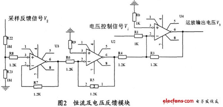
The output current range of the parameter current regulator is limited, and its precision is not high. Connecting the feedback adjustment type output current of the current-stabilized power source in series results in lower efficiency. The steady current source...
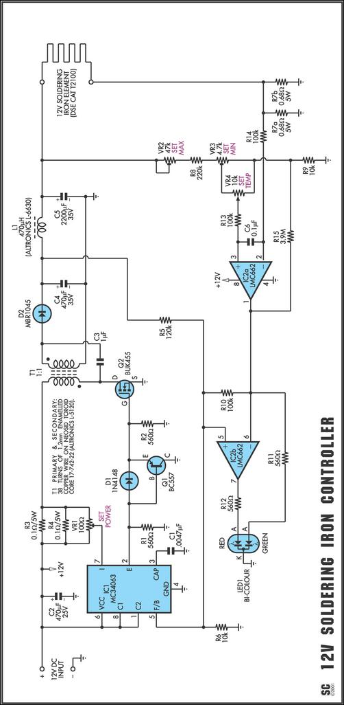
One reason commercial soldering stations are costly is that they typically require soldering irons with built-in temperature sensors, such as thermocouples. This circuit removes the necessity for a specialized sensor by detecting the temperature of a soldering iron heating...
This circuit is a double direction flash. Similar to Digital Ping-Pong 1, there is a movement of a lit dot, up and down along the LED's length. When the D16 lit the situation changes and there is a reverse...
For applications requiring numerous Analog to Digital channels or substantial program memory (up to 32K), this prototype board is ideal. It is designed for 40-pin PIC microcontrollers and includes a power supply circuit, a 20MHz crystal oscillator circuit, an...