
Jfet Chopper Circuit Circuit

The circuit employs a Junction Field Effect Transistor (JFET), specifically the MPF102, which is a common choice for low-noise applications due to its high input impedance and low distortion characteristics. In this configuration, the MPF102 functions as a chopper, converting the DC signal into an alternating signal that can be amplified effectively by subsequent stages in the amplifier.
The multivibrator formed by transistors Q1 and Q2 is essential for generating the necessary chopping frequency. This arrangement typically operates in astable mode, producing a square wave output that toggles between high and low states. The frequency of this output can be adjusted by varying the values of the associated resistors and capacitors in the multivibrator circuit, allowing for flexibility in the operation of the amplifier.
Resistor Rr plays a crucial role in biasing the JFET. By setting the appropriate bias level, Rr ensures that the MPF102 operates in its optimal region, minimizing distortion and improving linearity. This biasing technique is critical because it directly affects the performance of the chopper, influencing the overall gain and efficiency of the amplifier.
The AC coupling in the amplifier circuit allows for the isolation of the DC component of the input signal, enabling the amplification of the AC component without affecting the DC levels. This is typically achieved using coupling capacitors that block DC while allowing AC signals to pass through.
Overall, this circuit design effectively combines the functionalities of signal chopping and amplification, leveraging the characteristics of the MPF102 JFET and the multivibrator configuration to achieve desired performance metrics in audio and other signal processing applications. A JFET (MPF102) is used to chop a dc signal for amplification in an ac coupled amplifier. Q3 is the chopper element and Q1-Q2 forms the multivibrator to derive a chopping signal. Rr sets the bias on the FET to keep the drive to MPF102 as low as possible.
Related Circuits
This is an audio power amplifier that delivers 40 W at 8 ohms in Class A operation. The power transistors are continuously active, enabling a substantial current to flow. The audio power amplifier described operates in Class A mode, which...
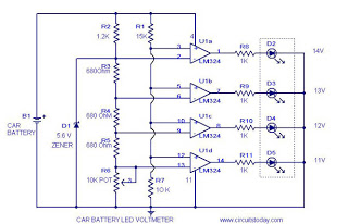
This circuit is a practical device that, when installed in a vehicle, displays the voltage of the car battery using an LED dot display. The meter circuit utilizes four comparators formed from a quad op-amp, specifically the LM324. The...
This document describes a 100 Watt inverter circuit that utilizes a minimal number of components. The circuit employs the CD 4047 integrated circuit (IC) from Texas Instruments to generate 100 Hz pulses, along with four 2N3055 transistors that drive...
This document presents plans for a simple ground plane antenna that is effective in the FM band (88-108 MHz). It is constructed from a small plastic disk. The 6 x 6 loop antenna, designed by Graham Maynard, is highlighted...
An FM transmitter circuit that utilizes a low power configuration, employing an operational amplifier as an audio preamplifier and a single transistor to function as the RF amplifier. This FM transmitter circuit is designed for low power applications, making...

This car audio amplifier circuit is based on the LA47536 audio amplifier integrated circuit designed by Sanyo. This audio amplifier circuit is specifically designed for car audio power amplifiers. The LA47536 car audio amplifier IC features four output channels...