
computer c64
The internal power supply circuit of the Commodore 64 is crucial for its operation, as it converts the 9V AC input into the necessary DC voltage levels required by the computer. The block diagram provides a clear representation of how the +12V and +9V outputs are generated, along with the TOD (Time of Day) clock signals.
The power supply unit typically consists of a transformer that steps down the voltage from the AC mains to 9V AC. This AC voltage is then rectified using diodes to produce a pulsating DC voltage. Capacitors are employed to smooth this pulsating voltage, providing stable DC outputs. Voltage regulators may be used to ensure that the output voltages remain constant under varying load conditions, protecting the internal components of the Commodore 64 from voltage fluctuations.
The +12V output is often used to power peripheral devices, while the +9V output serves the internal circuitry of the computer. The TOD clock signals are essential for maintaining time functions within the system, ensuring that the computer can accurately track time-related tasks.
The schematic diagram's resolution of 360 DPI in two colors allows for clear visualization of the circuit's components and connections, facilitating troubleshooting and repair. The partial translation into German may aid German-speaking technicians in understanding the circuit's functionality. The reference to the Commodore VIC-10 schematic indicates the interconnected history of these machines, highlighting the importance of accurate documentation in preserving knowledge about vintage computing hardware.A block diagram of the Commodore 64 internal power supply (how the +12V, +9V and TOD clock signals are generated from the 9V AC input). Taken from the SAMS C64 Troubleshooting Guide. Commodore 64 schematic diagram, scanned with 360 DPI, 2 colours. This seems to be the same (buggy) schematic that was published in the Commodore 64 Programmer`s Refer
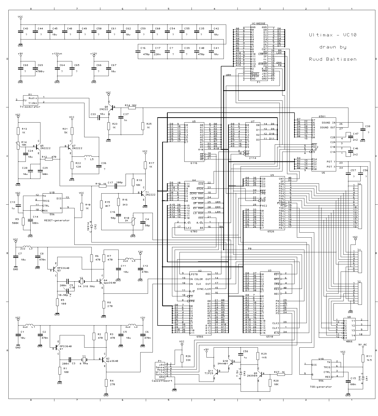
ence Guide, but has been partially translated into German. Commodore VIC-10, a. k. a. UltiMax a. k. a. "Vickie" schematic diagram, drawn by Ruud Baltissen. For more information on this extremely rare machine, see. See also 326100. png. 🔗 External reference
Related Circuits
The LED guard-rail tube, also known as the decorative tube, is an advanced LED illumination product designed for decorative purposes. It utilizes red, green, and blue LEDs as light sources, employing microelectronics and digital technology to create color chasing...
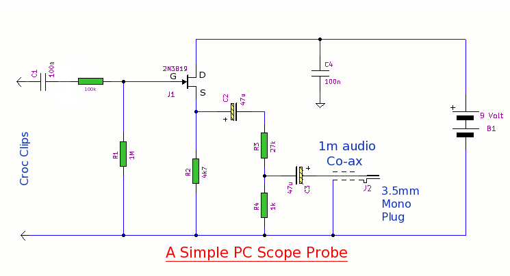
This simple PC scope probe functions as a FET follower, featuring high input impedance and low output impedance to match a microphone or line input socket on a PC or laptop. This design allows for practical examination of waveforms...
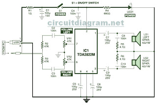
This is the circuit diagram of a USB-powered computer speaker, commonly referred to as multimedia speakers for PCs. The circuit features a single-chip design, operates on a low-voltage electrical power supply, is compatible with USB power from computers, and...

This is the circuit diagram of a USB-powered computer speaker, commonly known as multimedia speakers for PCs. The circuit features a single-chip design, operates on a low-voltage power supply, and is compatible with USB power from a computer. The USB-powered...
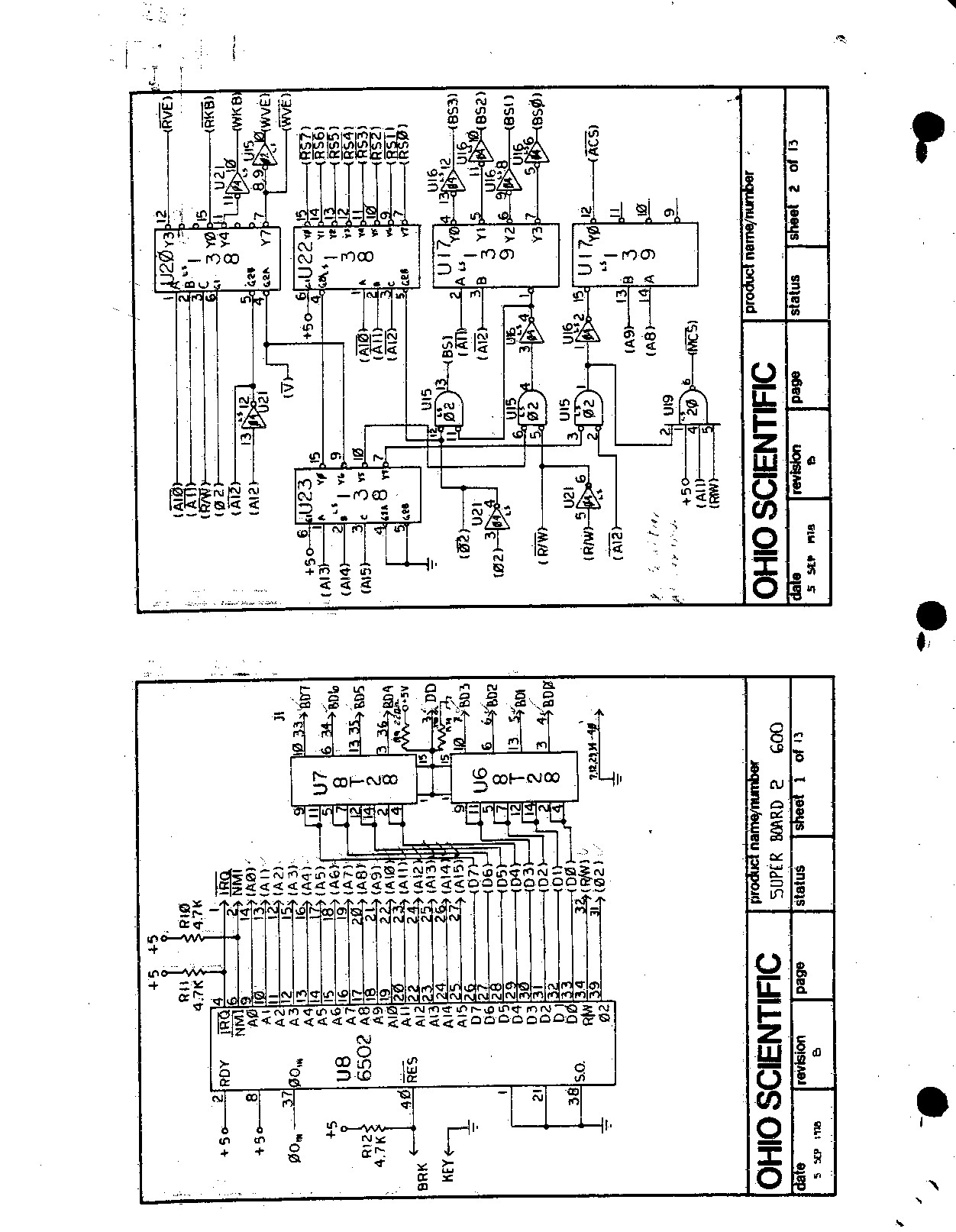
This machine was significant as it was the first real computer, an Ohio Scientific Superboard II, acquired in 1979. It is a 6502-based single-board computer featuring 8K of RAM and BASIC in ROM. The board is entirely self-contained, requiring...

When running large-scale software or games, a computer's internal temperature can increase significantly, especially during hot summer months. Although the machine is equipped with a CPU and graphics card fan, poor hot air circulation prevents immediate removal of heat...