
Connecting the Sharp IR Sensor

The circuit described involves a sensor with three wires: a red wire for power, a black wire for ground, and a yellow wire for signal output. The red wire is connected to a +5V power supply, providing the necessary voltage for the sensor to operate. The black wire is connected to Ground (GND), establishing a common reference point for the circuit.
The yellow signal wire is routed to analog pin A0 of a microcontroller, allowing the microcontroller to read the sensor's output. This output is likely an analog voltage that corresponds to the sensor's measurement. In parallel with the yellow signal wire, a 10k ohm resistor is connected to ground. This resistor serves as a pull-down resistor, ensuring that the analog pin A0 is held at a low logic level when the sensor is not actively sending a signal.
The configuration of the circuit is essential for proper sensor operation and accurate data acquisition by the microcontroller. The choice of a 10k ohm resistor is typical for pull-down applications, providing sufficient impedance to prevent floating inputs while minimizing power consumption. Proper connections and component values are crucial for the reliable performance of the sensor and the overall circuit functionality.The red wire of the sensor connects to +5 volts, the black wire connects to Ground (GND), and the yellow signal wire connects to analog pin A0 through the same bus as the 10k ohm resistor that is connected to ground. 🔗 External reference
Related Circuits

The maximum input voltage is 10V. An operational amplifier (op-amp) is used to provide a reference voltage of 10V, with its stability primarily determined by the characteristics of a temperature-compensated Zener diode (IS2192). The Zener voltage (Vz) can be...
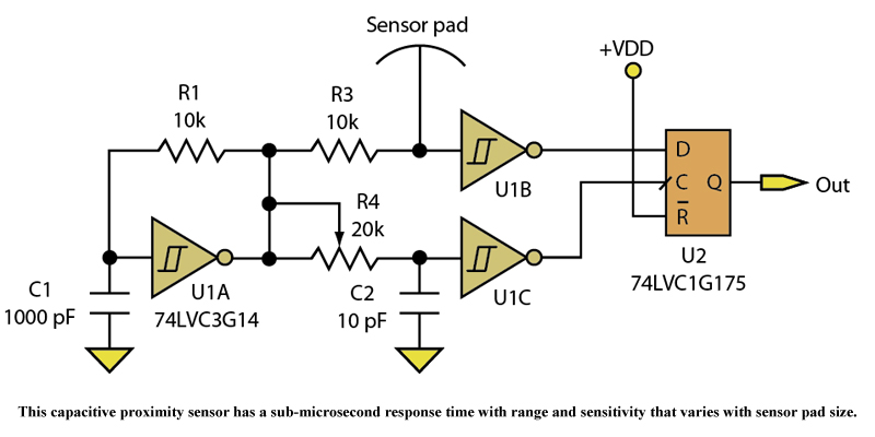
Three devices in a quad Schmitt Trigger and a Flip-Flop create a simple yet sensitive proximity sensor. The described circuit utilizes three devices from a quad Schmitt Trigger configuration alongside a Flip-Flop to construct a proximity sensor. The Schmitt Trigger...
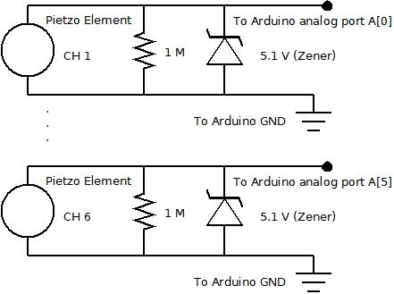
The piezo element is connected solely to Channel 1 (Arduino A[0] port). Channels 1 through 6 are linked to female mono jacks, with the ground (GND) wiring arranged in series from jacks 1, 2, and 3, continuing to the...
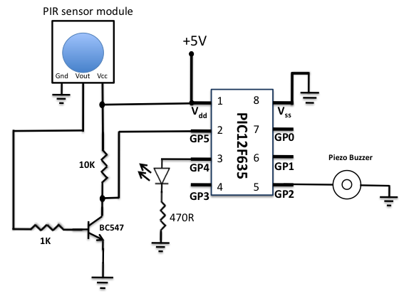
A diode is used in series to drop the voltage to 5.4 V, as the operating voltage for the PIC microcontroller should be below 5.5 V. Additionally, the diode provides protection to the circuit in case of reverse polarity...

This is a simple update to Mr. Hareendran's PIR Sensor Security Light circuit. It has a shortcoming that limits the relay voltage to approximately 3.3V. While this may function with some 5V relays, it will not function with all. The...

The simple pressure sensor alarm is constructed using a few inexpensive and readily available components. The operation of this circuit is straightforward and self-explanatory. When powered by a 9V compact battery, the active piezo sounder at the output of...
Warning: include(partials/cookie-banner.php): Failed to open stream: Permission denied in /var/www/html/nextgr/view-circuit.php on line 713
Warning: include(): Failed opening 'partials/cookie-banner.php' for inclusion (include_path='.:/usr/share/php') in /var/www/html/nextgr/view-circuit.php on line 713