
Security Light & Switch with PIR Sensor Update

The PIR (Passive Infrared) Sensor Security Light circuit is designed to activate a light source based on motion detection through infrared signals. The original design by Mr. Hareendran incorporates a relay that switches on the light when motion is detected. However, a critical limitation in the circuit arises from the relay voltage being restricted to approximately 3.3V. This voltage level may be sufficient for certain low-voltage relays, but it does not guarantee compatibility with all 5V relays, which are commonly used in similar applications.
To enhance the functionality and reliability of the circuit, it is recommended to redesign the relay driver stage to accommodate a higher voltage level. This can be achieved by integrating a transistor-based driver circuit that can handle the required current and voltage for 5V relays. The transistor can be used to switch the relay on and off based on the output from the PIR sensor, ensuring that the relay operates correctly regardless of its specifications.
Additionally, incorporating a flyback diode across the relay coil is advisable to protect the circuit from voltage spikes generated when the relay is deactivated. This diode will allow the inductive kickback to dissipate safely, preventing potential damage to the PIR sensor and other components in the circuit.
Overall, by addressing the voltage limitation and enhancing the relay driver stage, the PIR Sensor Security Light circuit can be made more versatile and reliable, ensuring compatibility with a wider range of relay types and improving the overall performance of the security light system.This is a simple update to Mr. Hareendran s PIR Sensor Security Light circuit. It has a shortcoming limits the relay voltage to approximately 3.3V. While this may function with some 5V relays, it will not function with all. The nature of.. 🔗 External reference
Related Circuits
Hens require adequate illumination to increase egg production rates. To counteract the reduced winter sunlight, poultry farms commonly utilize artificial lighting in coops. For instance, the circuit depicted in Figure 297 can automatically provide light at night. The light...

This is an intriguing 555 timer circuit designed to entertain and engage individuals while studying electronics in educational settings. Commonly referred to as a clap switch circuit, it operates as a sound-controlled flip-flop. This sound-controlled light can also function...

This submersible sonar positioning apparatus primarily comprises dual-opposed ultrasonic transducers that are alternately excited, with the return signals processed and displayed for observation and measurement. Typical transmitter frequencies range from 50 to 200 kHz, and pulse widths can be...
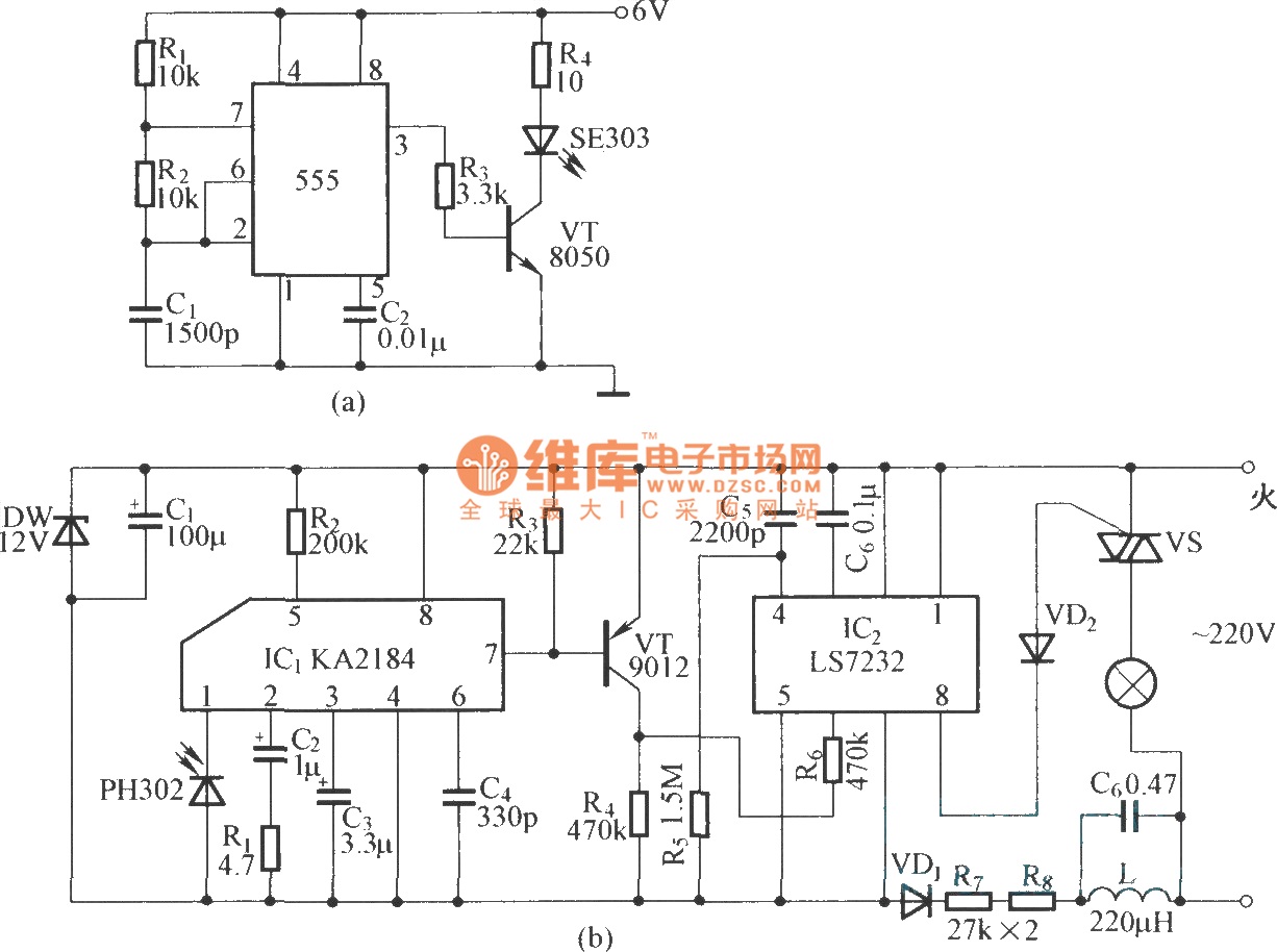
This is an infrared emission circuit diagram. The NE555 circuit generates a 40 kHz pulse, which is sent by the infrared emission control SE303 after being amplified by VT. The remote receiver and infrared dimming circuit are composed of...

The circuit utilizes six 12-volt lead-acid batteries to power the load. Three batteries are connected in series to generate 36 volts, while the other three are connected in parallel to maintain 12 volts. The total discharge current is 30...

A circuit that can automatically turn off the headlights or lamps of a vehicle after a preset time. This light switching circuit is constructed using a 555 timer integrated circuit (IC). The described circuit utilizes the 555 timer IC in...