
constant current Basic schematic help
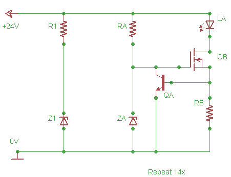
The proposed lighting circuit is designed to operate an indoor garden using a 24V input source, which is regulated down to 20V for optimal performance. The circuit incorporates a series array of LEDs (LA) that has a total voltage drop of approximately 19.8V, ensuring that the LEDs receive adequate voltage for illumination without exceeding their ratings. The components R1 and Z1 are critical in limiting the overall voltage of the circuit to 20V, protecting the LEDs from overvoltage conditions.
The upper section of the circuit, identified by the "Repeat 14x" label, implements a constant-current configuration. This design is adapted from an instructable and is structured to repeat 14 times, allowing each segment to draw approximately 0.02A. This repeated configuration ensures uniform brightness across all LED segments while maintaining efficiency.
The components RA and ZA serve a specific purpose in regulating the gate voltage of transistor QB to approximately 5V. This raises a question about whether this limitation extends to the entire circuit, potentially affecting the voltage drop across the LED array. It is essential to clarify that while RA and ZA control the gate voltage, they do not necessarily limit the entire circuit to 5V. Instead, they ensure that QB operates within its safe parameters, allowing the rest of the circuit, including the LED array, to function correctly at their designed voltage levels.
RB, calculated to be 27 ohms with a power rating of 1/4 W, is an important resistor in the circuit that aids in setting the current through the LEDs. It is derived from the constant current formulas provided in the instructable, ensuring that the current remains stable across the LED array.
In summary, the circuit requires QA, QB, and RB for proper operation. The gate of QB and the collector of QA can indeed be connected to the R1/Z1 circuit, allowing for effective voltage regulation while maintaining the desired current through the LED segments. This configuration will provide reliable lighting for the indoor garden while ensuring the longevity of the components involved.Design a lighting circuit for an indoor garden, and I`m not understanding things that seem like they`re really basic, so I need some help. The schematic I`m referencing is: I have a 24V input source which I`d like to limit to 20V. LA is a series array of LEDs such that the total voltage drop across the series is ~19. 8V. R1 and Z1 are designed to limit the circuit to 20V. The portion of the circuit after that (the area above the "Repeat 14x" label) is a constant-current circuit as adapted from this instructable, and will be repeated a total of 14 times. Each of those will draw approximately 0. 02A. My confusion stems from the presence of RA and ZA, that, in tweak 3 of the constant current instructable, limits the input to the gate of QB to about 5V.
Doesn`t it also limit the entire circuit to 5V, including the drop across the LED array RB was calculated to be 27 ohm 1/4 W from the formulas provided in the constant current instructable; do I only need QA, QB, and RB in the circuit, and then connect the gate of QB and collector of QA to the R1/Z1 circuit 🔗 External reference
Related Circuits
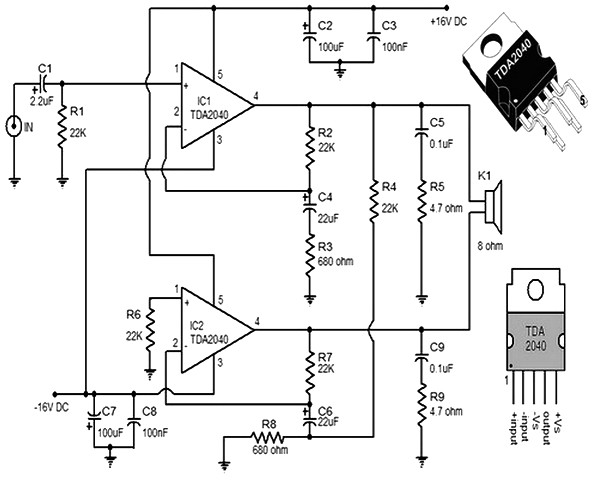
This small and compact stereo amplifier is powerful and can easily replace a broken amplifier or be used in new constructions, or to create an active speaker, when combined with a preamplifier. Its remarkable features make it a true...
This circuit can be utilized by individuals, such as a gentleman summoning his butler, a manager calling for his secretary, or, as in the author's case, to call children down for dinner without raising one's voice over the noise...
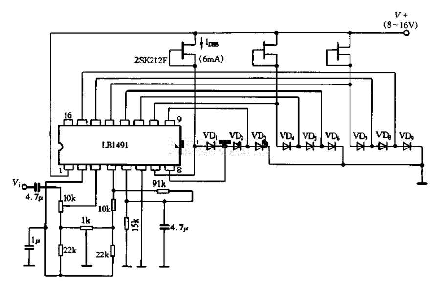
A display tube utilizing a constant current circuit to ensure a steady flow through the tube. The display tube operates on the principle of maintaining a constant current to achieve consistent brightness and performance. The circuit typically comprises a current...
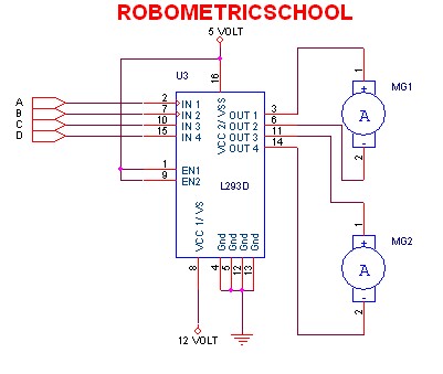
The electronic schematic of a DC motor driver using the L293D, as illustrated in Figure 2, enables the control of two DC motors continuously. It allows for one motor to rotate clockwise while the other rotates counterclockwise. Additionally, all...
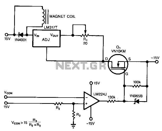
The circuit powers the load through the input of the regulator rather than its output. Due to the presence of a constant dummy load (R1) at the regulator's output, it attempts to draw a constant amount of current, regardless...
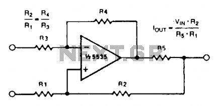
A simple voltage-to-current converter is illustrated. The output current is given by 0t or Vjn/R. For negative currents, a PNP transistor can be employed, and for improved accuracy, a Darlington pair can replace the transistor. With meticulous design, this...