
Constituted by the ISO113 0 ~ 20mA current loop isolation drive circuit diagram
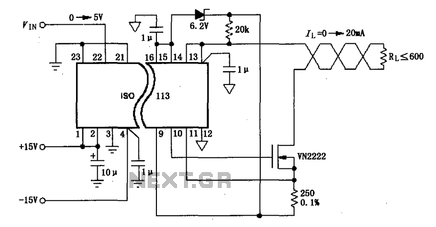
The ISO113 current loop isolation drive circuit is designed to provide electrical isolation between the input and output, ensuring that any noise or interference present in the input signal does not affect the output. This is particularly important in industrial environments where electromagnetic interference (EMI) is common. The twisted pair configuration of the load resistor (RL) further enhances noise immunity, allowing for stable current transmission over extended distances.
The XTR101 plays a crucial role in this circuit by converting the input voltage signal into a proportional current output within the 0 to 20 mA range. This current is standard in many industrial applications, allowing for compatibility with a wide range of sensors and devices. The 4 to 20 mA current loop is a widely accepted standard for transmitting analog signals, where 4 mA typically represents the minimum measurement and 20 mA the maximum, facilitating easy interpretation of the signal levels.
The RCV420 receiver is designed to accurately detect the current flowing through the loop and convert it into a voltage signal suitable for further processing. This voltage signal can then be utilized by various control systems or monitoring equipment. The ISO103 isolation amplifier provides additional isolation, ensuring that any variations in the load do not affect the measurement accuracy or the integrity of the signal being processed.
Overall, this circuit configuration is ideal for applications requiring reliable and accurate signal transmission over long distances, ensuring that the integrity of the data is maintained while minimizing the risk of interference. As shown in FIG constituted by ISO113 0 ~ 20mA current loop isolation drive circuit. VIN signal input ISO113 isolation amplified output 0 ~ 20mA current to the load through the twisted pair RL, the 4 ~ 20mA current loop precision receivers RCV420 receives converted into a voltage signal to the isolation amplifier ISO103. The main features of this circuit is using XTR101 input signal into 0 ~ 20mA current, long-distance transmission current signals without susceptible to interference.
Related Circuits

The Mini AV Test Box circuit is designed with simplicity and efficiency in mind. It consists of three main sections, which are clearly delineated in the schematic. The primary components utilized in this circuit include the 7805 voltage regulator,...
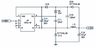
The following file is an application note describing the two stages of an electronic ballast for a 250 W HID metal halide lamp. The components include. The application note outlines a two-stage electronic ballast designed specifically for a 250 W...
The circuit designed for distortion measurements eliminates the fundamental frequency of 1 kHz, enabling the assessment of the residual harmonic levels. Initially, a true RMS meter is employed to measure the 1-kHz input level (E^) by positioning the switch...
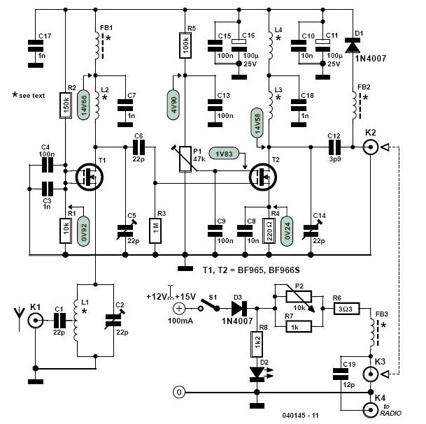
This high-performance two-stage antenna amplifier for the VHF FM broadcast band, when paired with a quality directional antenna, allows for the reception of distant (DX) stations. It significantly enhances the reception of FM signals that may otherwise be considered...
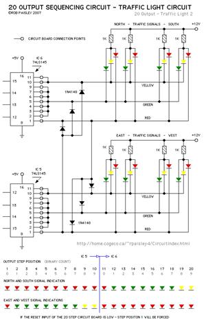
The current application involves the use of the VHDL hardware description language for designing a traffic light system controller circuit. This design is implemented within the Altera MAX PLUS EDA software environment, which facilitates compilation, simulation, and programming for...
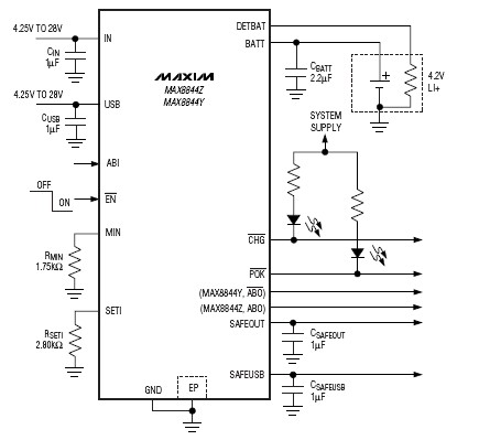
The MAX8844 lithium-ion charger integrated circuit (IC) from Maxim Semiconductors facilitates the design of a simple and efficient charger circuit for a single-cell lithium-ion battery. This charger integrates a current-sense circuit, a MOSFET pass element, thermal-regulation circuitry, and eliminates...