
Circuit Diagram for 250 W HID Metal Halide Electronic Ballast
The application note outlines a two-stage electronic ballast designed specifically for a 250 W high-intensity discharge (HID) metal halide lamp. This ballast serves to regulate the electrical power supplied to the lamp, ensuring optimal performance and efficiency.
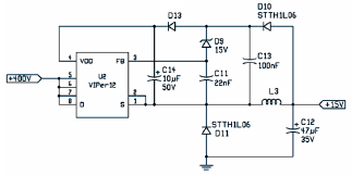
The first stage of the ballast typically involves a power factor correction circuit, which enhances the efficiency of the power supply. This stage may include components such as inductors, capacitors, and rectifiers that work together to convert the AC input voltage into a more stable DC voltage. The power factor correction stage is crucial for minimizing energy losses and improving overall system performance.
The second stage of the ballast is responsible for providing the necessary starting voltage and operating current to the metal halide lamp. This stage may utilize a high-frequency inverter circuit, which converts the DC voltage back into a high-frequency AC signal. The inverter is composed of various electronic components, including transistors or MOSFETs, which switch on and off at a high rate to generate the required output frequency. The output stage may also include a transformer to step up the voltage to the level required for ignition and sustained operation of the lamp.
In addition to the core components, the application note may detail various protective features integrated into the ballast design, such as overcurrent protection, thermal management strategies, and fault detection systems. These features are essential for ensuring the longevity and reliability of the ballast and the HID lamp.
Overall, the electronic ballast is a critical component in the operation of HID metal halide lamps, providing the necessary electrical characteristics to ensure efficient lighting performance while maintaining safety and reliability in various applications.The following file is an application note describing the two stages of electronic ballast for a 250 W HID metal halide lamp. The components include.. 🔗 External reference
Related Circuits
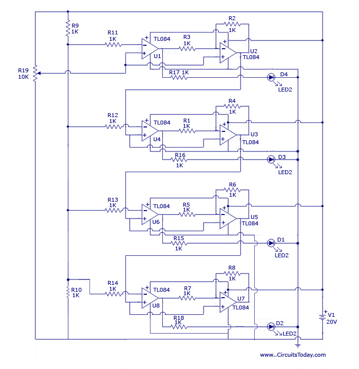
The design originated from the interest in discovering a new technique for analog to digital conversion. The two types of ADC (Analog to Digital Converter) that influenced the development of this circuit are the Flash Type ADC and the...
The image depicts a proximity switch circuit that includes the HMC1001 Hall effect sensor, an operational amplifier (AMP04), and a light-emitting diode (LED). In this configuration, the operational amplifier functions as a comparator. When a magnet with a length...

The DC motor E inversion control circuit utilizes a loop configuration with various relay contacts. It employs a single set of normally open/normally closed relay contacts. When both inputs A and B are low, relay KI is activated. In...
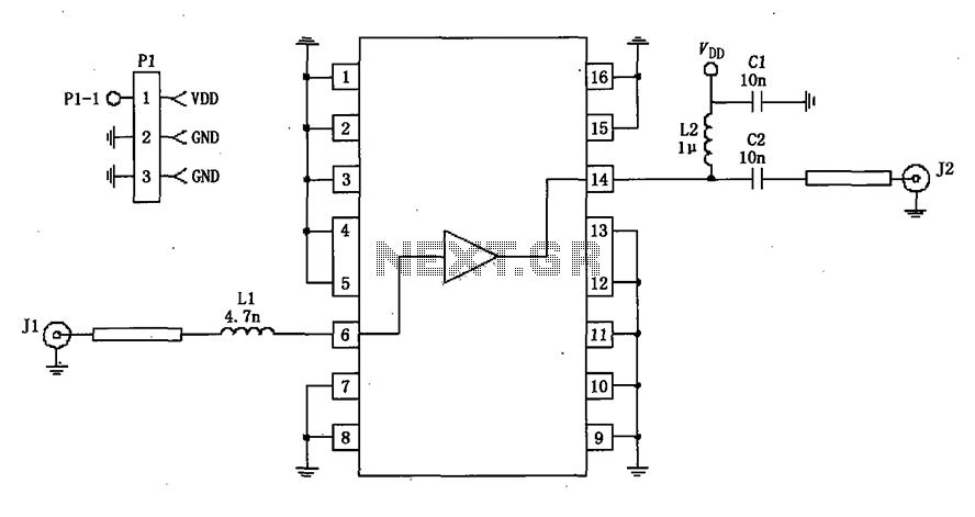
A 50-ohm impedance is illustrated in the RF2320 linear amplifier circuit, which is configured for input and output using transmission lines and inductive or capacitive components to create a matching network. The RF2320 linear amplifier circuit is designed to operate...

A voltage-controlled oscillator (VCO) operates similarly to a voltage-to-frequency converter (VFC). Its output frequency is determined by a control voltage input. In the circuit diagram, 'd' represents the amplifier input voltage, which is set to 0.6V, while 'h' denotes...
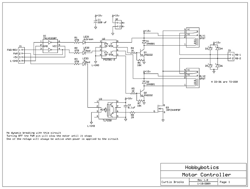
Develop a cost-effective high-current circuit that utilizes PWM. The design includes flyback diodes to protect the MOSFET from the back EMF generated by the motor when the power is switched on and off via the PWM signal. This configuration...
Warning: include(partials/cookie-banner.php): Failed to open stream: Permission denied in /var/www/html/nextgr/view-circuit.php on line 713
Warning: include(): Failed opening 'partials/cookie-banner.php' for inclusion (include_path='.:/usr/share/php') in /var/www/html/nextgr/view-circuit.php on line 713