
schematic long range fm

The transmitter circuit features a well-defined architecture designed to enhance signal transmission capabilities in the VHF band. The initial stage, utilizing the BF494 transistor, serves as the oscillator, generating a variable frequency signal that can be modulated with audio input through the varicap diode. This modulation capability allows for effective transmission of audio signals alongside the carrier wave.
The subsequent amplification stage, employing the 2N3866 transistor, significantly boosts the output power. The design ensures that the final output, achieved at the collector of T2, reaches levels sufficient for effective communication over a distance of up to 2 kilometers. The careful selection of components, such as the specific wire gauges for coil winding, plays a critical role in achieving the desired resonant frequencies and impedance matching required for optimal performance.
The inclusion of a heat sink for transistor T2 is essential to prevent overheating during prolonged operation, which could otherwise lead to circuit failure. The use of a rechargeable battery pack ensures a stable power supply, which is crucial for maintaining consistent performance while minimizing hum and noise in the output signal.
The circuit's layout should prioritize compactness and shielding, particularly for the oscillator stage, to minimize interference and enhance overall signal integrity. The assembly on a glass epoxy board not only provides structural stability but also contributes to the reduction of parasitic capacitance, which can adversely affect the oscillator's performance.
In summary, this transmitter circuit is a well-engineered solution for educational applications, demonstrating the principles of RF amplification, frequency modulation, and circuit design. Its specifications and operational guidelines underscore the importance of careful assembly and component selection in achieving reliable and effective performance.The power output of most of these circuits are very low because no power amplifier stages were incorporated. The transmitter circuit described here has an extra RF power amplifier stage, after the oscillator stage, to raise the power output to 200-250 milliwatts.
With a good matching 50-ohm ground plane antenna or multi-element Yagi antenna, this t ransmitter can provide reasonably good signal strength up to a distance of about 2 kilometers. The circuit built around transistor T1 (BF494) is a basic low-power variable-frequency VHF oscillator. A varicap diode circuit is included to change the frequency of the transmitter and to provide frequency modulation by audio signals.
The output of the oscillator is about 50 milliwatts. Transistor T2 (2N3866) forms a VHF-class A power amplifier. It boosts the oscillator signals` power four to five times. Thus, 200-250 milliwatts of power is generated at the collector of transistor T2. For better results, assemble the circuit on a good-quality glass epoxy board and house the transmitter inside an aluminum case. Shield the oscillator stage using an aluminum sheet. Coil winding details are given below:L1 - 4 turns of 20 SWG wire close wound over 8mm diameter plastic former.
L2 - 2 turns of 24 SWG wire near top end of L1. (Note: No core (i. e. air core) is used for the above coils)L3 - 7 turns of 24 SWG wire close wound with 4mm diameter air core. L4 - 7 turns of 24 SWG wire-wound on a ferrite bead (as choke)Potentiometer VR1 is used to vary the fundamental frequency whereas potentiometer VR2 is used as power control.
For hum-free operation, operate the transmitter on a 12V rechargeable battery pack of 10 x 1. 2-volt Ni-Cd cells. Transistor T2 must be mounted on a heat sink. Do not switch on the transmitter without a matching antenna. Adjust both trimmers (VC1 and VC2) for maximum transmission power. Adjust potentiometer VR1 to set the fundamental frequency near 100 MHz. This transmitter should only be used for educational purposes. 🔗 External reference
Related Circuits
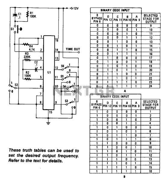
Using an RC oscillator, an up to 24-stage ripple counter (O) 16777216 or 2^24, and a 0.1-Hz count rate, with R2 = 39 kΩ, C2 = 0.001 µF, and R4 = 220 kΩ, the count cycle would take approximately...

A simple 12V battery charger circuit can be designed using a TIP3055 power transistor to limit the current to the battery. The circuit turns off when the battery voltage reaches approximately 14V or if the current exceeds 2A. This...
Electronic circuits are presented in schematic form. A schematic is essentially a map that illustrates the path of current through various components. Each component is represented by a symbol, typically accompanied by a label or a value, or both....

The circuit diagram illustrates a simple long-range AM transmitter built using three transistors. With proper tuning and a compatible antenna, this transmitter can broadcast signals over a distance of up to 2 kilometers. The audio signal intended for transmission...
This is a convenient design for a transistor tester. The advantage of this circuit is that transistors can be tested without actually doing the circuit soldering. The tester uses two ICs: an NE 555 timer and a CMOS IC...

This unit utilizes a dual trace oscilloscope with X-Y functionality as a display to test and demonstrate the operation of circuits and components such as transistors, diodes, zener diodes, and both terminated and unterminated transformers. A low-frequency sine wave...