
Adjustable-sensitivity field-strength indicator
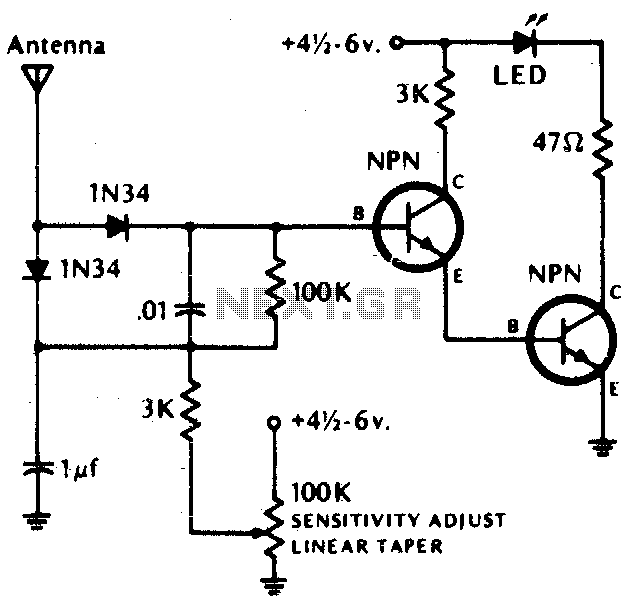
The circuit described is a simple RF field strength indicator that utilizes an LED to provide a visual indication of the RF field strength exceeding a predetermined threshold. The core component of this circuit is the LED, which activates when the RF field strength surpasses the set levels. The use of germanium diodes is suggested for their low forward voltage drop, which enhances the sensitivity of the circuit to low RF signals.
In this design, an RF field sensor is likely integrated with a voltage divider or a comparator circuit to detect the RF signal strength. The output from this sensor is fed into the base of an NPN transistor, such as the 2N2222, 2N3393, or 2N3904. These transistors act as switches, controlling the current flow to the LED based on the input signal from the RF sensor.
The choice of NPN transistors allows for efficient switching and amplification of the RF signal. When the RF field strength exceeds the set threshold, the transistor turns on, allowing current to flow through the LED, causing it to light up. A resistor may be included in series with the LED to limit the current and protect the LED from excessive current that could lead to damage.
Additional components may include capacitors for filtering and stabilizing the input signal, as well as potentiometers for adjusting the sensitivity of the circuit. This design is suitable for applications where monitoring RF fields is crucial, such as in wireless communication systems, RF testing environments, and electromagnetic compatibility assessments.The LED lights if the rf field is higher than the pre-set field strength level. Diodes should be germanium Transistors (NPN) = 2N2222, 2N3393, 2N3904 or equivalent. 🔗 External reference
Related Circuits

This simple circuit indicates the status of a phone, including Line OK, Dialing, and Call Attended. It also features a locking mechanism to block outgoing calls while allowing incoming calls, preventing misuse of the telephone. The circuit requires only...
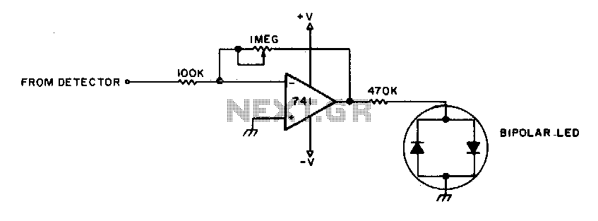
To adjust, tune into a station and adjust the I"M pot for a null. Then ask the station to modulate and fine-tune so modulation peaks do not light the LEDs. Stations are properly tuned when neither LED is lit. The...
The image depicts an ultrasonic liquid level indicator circuit. This circuit consists of an ultrasonic transmitter circuit and a receiver circuit. The ultrasonic transmitter circuit includes a 555 timer, resistor R1, variable resistor W1, capacitor C1, and the ultrasonic...
This circuit is designed to indicate the power output level of any audio amplifier. It is simple, portable, and displays three power levels that can be set to any desired value. The circuit operates by utilizing a combination of resistive...
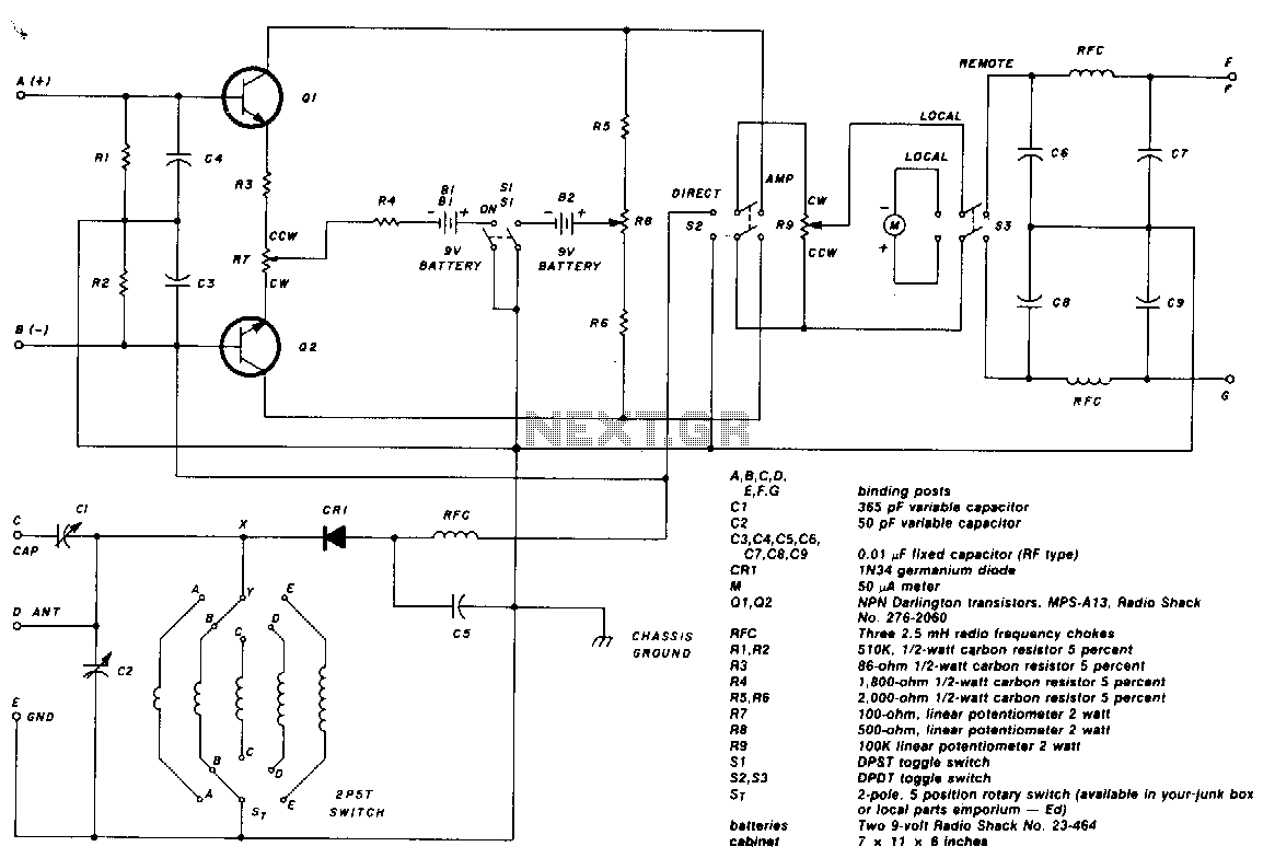
The two-pole, five-position switch, coils, and 365-pF variable capacitor cover a range from 1.5 to 30 MHz. The amplifier uses Darlington npn transistors whose high beta of 5000 provides high sensitivity, with SL used as the amplifier on/off switch....
When the input voltage is 0 the LED glows. The LED stops glowing when the voltage rises to the level determined by R2. Reverse + and - pins to reverse operating mode. To set voltage at which LED goes...