
Continuity Tester For Low-Resistance circuits
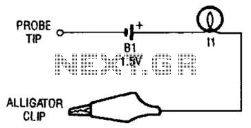
The continuity tester is a fundamental tool used in electrical diagnostics to determine whether a circuit is complete or if there are breaks in the path. The basic configuration includes a battery, which serves as the power source, and a lamp that acts as an indicator. When the circuit is complete, current flows through the lamp, causing it to illuminate.
The alligator clip is designed for easy attachment to various points in a circuit, allowing for efficient testing without the need for additional tools. The probe tip is used to make contact with other components or wires, enabling the user to check continuity at different locations.
In a typical setup, the battery voltage is chosen based on the specifications of the lamp to ensure adequate brightness when the circuit is complete. Commonly, a 9V battery is used with a small bulb, such as an LED or a miniature incandescent bulb, to provide a clear visual indication of continuity.
The circuit can be represented schematically with the battery symbol connected in series to the lamp symbol, with lines indicating the connections to the alligator clip and probe tip. The alligator clip and probe tip are usually depicted as separate terminals, allowing for clear identification of the testing points.
In terms of safety and usability, it is essential to ensure that the voltage used is appropriate for the components being tested to prevent damage. Additionally, the design should incorporate a durable casing for the battery and lamp assembly to withstand regular use in various environments.
Overall, the continuity tester is a simple yet effective device, crucial for troubleshooting electrical systems, ensuring that circuits are intact and functioning correctly. The continuity tester is little more than a battery and a lamp connected iri series, with one end of the string terminated in an alligator clip, and the other end connected to the probe tip. 🔗 External reference
Related Circuits
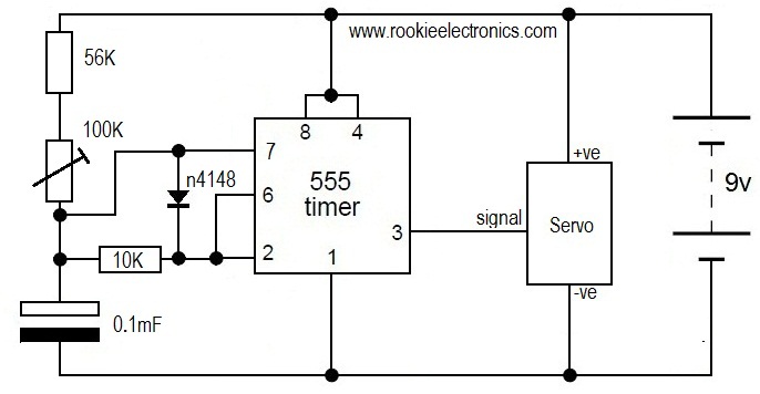
This is likely the simplest circuit to test a servo. It tests the speed of the servo using a potentiometer to control the speed. By applying a low voltage, such as 4.5V, and adjusting the potentiometer value, the position...

A crystal tester circuit is straightforward, comprising only an oscillator and a detector. This circuit utilizes a single transistor for the oscillator. The crystal tester circuit is designed to evaluate the performance and functionality of crystals, which are essential components in...
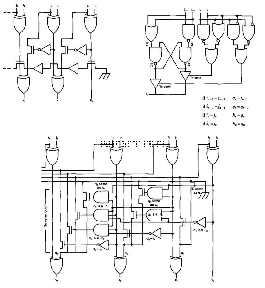
Some circuits that add binary numbers experience time delays due to carry propagation. This issue has been partially addressed by the carry look-ahead adder. However, the complexity of this method typically limits its application to no more than 4...
This tester, the logic level digital signals indicate on a 7-segment display. The display shows an H as the input signal is high. When the signal is low, the display shows an L on. If the input is open,...
Frequently, there are situations where the need arises to utilize a Zener diode, yet the operational voltage is unknown. Often, the characteristics or type inscribed on the diode are not legible. Zener diodes are essential components in electronic circuits, primarily...
The circuit utilizes a 4-bit encoder to generate data, which is then modulated using an RF modulator for transmission. On the receiving end, the signal is demodulated, and a decoder retrieves the 4-bit data. The pin configuration for the...