
Speed Controller with PIC16F84-04/SO
The described controller is a prototype designed for use in a model aircraft, specifically optimized to operate with a battery pack consisting of 7 cells. This configuration likely indicates a nominal voltage of approximately 24.5 volts if the cells are nickel-metal hydride (NiMH) or around 25.9 volts for lithium polymer (LiPo) cells, assuming typical cell voltages of 3.7 volts per LiPo cell and 1.2 volts per NiMH cell.
The Graupner-Speed 600 motor is known for its robustness and efficiency in model aircraft applications. It typically operates at a voltage range that aligns well with the output from a 7-cell configuration, providing adequate power for various flight maneuvers. The controller must be capable of managing the motor's speed and direction, likely incorporating pulse-width modulation (PWM) techniques to regulate power delivery and enhance efficiency.
In designing the electronic schematic for this controller, several key components are essential. A microcontroller or dedicated motor controller IC would serve as the brain of the system, interpreting input signals from the pilot's transmitter and adjusting the PWM signal accordingly. Additionally, protective circuitry such as overcurrent protection, thermal shutdown, and voltage regulation may be integrated to ensure safe operation under varying load conditions.
The power stage of the controller would include MOSFETs or IGBTs capable of handling the motor's current requirements while minimizing losses. Proper heat dissipation methods, such as heat sinks or active cooling, should be considered to maintain optimal operating temperatures during prolonged use.
Signal conditioning components, including capacitors and resistors, would be necessary to filter noise and stabilize the control signals, ensuring reliable communication between the microcontroller and the power stage. Furthermore, feedback mechanisms such as current sensors could be implemented to provide real-time data to the controller for enhanced performance and safety.
Overall, the combination of these elements results in a sophisticated electronic controller capable of delivering precise motor control in demanding model aircraft applications.The controller is a prototype and works well in my plane with 7 cells and a Graupner-Speed 600. 🔗 External reference
Related Circuits
The circuit features four pins labeled "Controller pin 1," "Controller pin 2," "Controller pin 3," and "Controller pin 4," which are responsible for controlling the motion and direction of the stepper motor based on the step sequence programmed into...
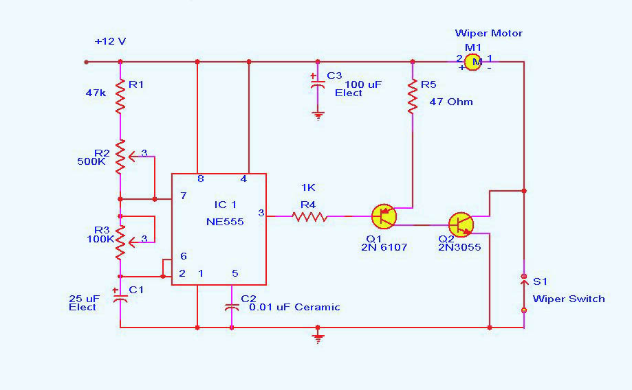
DC motor control circuit using NE555. The 555 timer circuit has numerous applications. For those unfamiliar with its functionalities, an authoritative book can provide valuable insights. CircuitsToday offers an online store featuring reviews of three highly recommended books that...
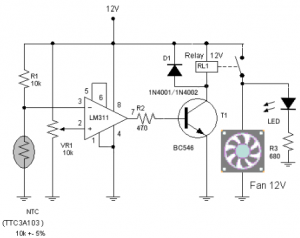
The circuit schematic diagram of a fan speed control system that activates only when necessary. When the transistor heats up, the fan will automatically turn on. The fan speed control circuit operates based on the temperature of the transistor, utilizing...
This is an audio-controlled lamp circuit. This circuit requires a low voltage input, such as from pre-amplifiers, tone control, or general audio line level output. The audio-controlled lamp circuit is designed to activate a lamp in response to audio signals....
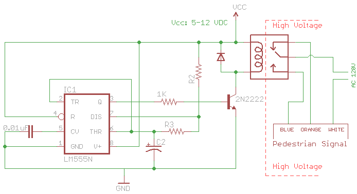
The signal consists of three wires: common, "walk," and "don't walk." This document outlines the operation of the unit's countdown feature. The information and examples provided here are applicable to other models and brands of signals. The signal was...
A relay-based on/off controller on the other hand can be very efficient. A typical relay has a contact resistance of 3 milliOhm. At 20A, this translates to a voltage drop of 0.06 volts, with a power loss of 1.2W....