
Control Ladder retract mechanism work
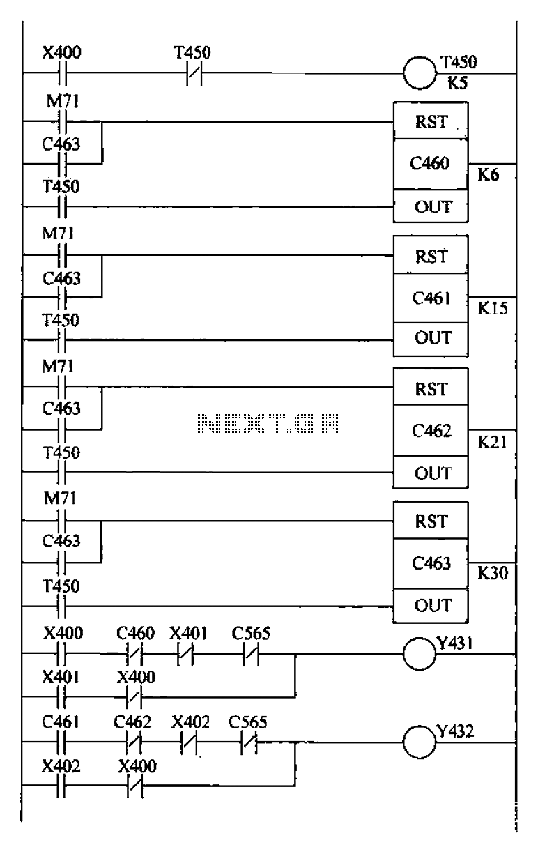
The bridge crane control system is designed using a Programmable Logic Controller (PLC) in a ladder logic format to automate the operation of the crane, enhancing efficiency and reliability. The initialization phase is crucial, as the internal relay M71 triggers a reset for the counters (C460-C463), ensuring that the system starts from a known state. The automatic operation is initiated by closing switch S1, which activates the crane's movement through the Y431 coil. The integration of timers, particularly T450, plays a vital role in timing the operations, producing a pulse every 5 seconds to manage the scanning of counters.
The counters function as critical elements in controlling the retract mechanism. The operation of the crane is carefully sequenced; for instance, when C460 counts within a specified range (1-6), the system deactivates the Y431 coil, halting the crane's movement. This safety feature prevents unintended operation during the retract phase. The second phase of operation involves C461 and C462, which manage the retraction process by controlling the Y432 coil. The timing intervals, such as the 45 seconds and 30 seconds, are strategically set to ensure smooth transitions between operations, minimizing mechanical stress and optimizing performance.
In the final phase, C463 acts as a reset mechanism, allowing the system to recycle and start a new operational cycle. The PLC's ability to manage these intricate sequences efficiently demonstrates its advantages over traditional control systems, such as reduced complexity and enhanced operational reliability. The design not only streamlines crane operations but also significantly reduces the manual labor involved, thereby improving overall productivity and safety in crane operations. The implementation of this PLC-based control system reflects a modern approach to industrial automation, aligning with contemporary standards for efficiency and effectiveness in material handling applications. Bridge crane control PLC ladder design Detection retract mechanism ladder hide programming manual and automatic operation of two run automatically follows Runtime: 1) When the PLC work boot, initialization pulse generated by internal relay M71, so each counter (C460-C463) reset. 2) When the automatic operation switch Sl is closed, X400 normally open contact closure, Y431 coil connected machine retreat plum actuator forward, then the contactor is energized, the crane started to move} Also, all timers, counters start work, the timer T450 produces a pulse every 5s, a hold time of a pulse of the scan period, supplying a scanning signal to the counter.
3) When the 0160 count to 1-6, C460 normally closed contacts open, so Y431 coil power, retract mechanism stops. 4) a few 45s, C461 counter to 15,0461 normally open contact closure, Y432 coil connected, cranes began to recede; to work after 30s, C462 counter to 21, C462 normally open contacts open, Y432 coil oFF, the back stop.
5) After a break 45s, C463 counts to 30, C463 normally open contact closure, so that all the counter is reset, and counting resumes fork into the second cycle. (4) Conclusion inverted by using PLC to control the operation of the bridge overweight machine to detect in the field can be efficiently completed, can fully reflect the PLC has the function, high reliability, programming is simple, easy to use, small size and other advantages.
Using PLC can also solve a lot of trouble under the traditional control manipulated, including the opening and closing of the motor and the motor when lifting the grab just closed loading lift pheasant in the same step and other issues. At the same time, it can also reduce labor intensity, improve work performance crane.
Related Circuits
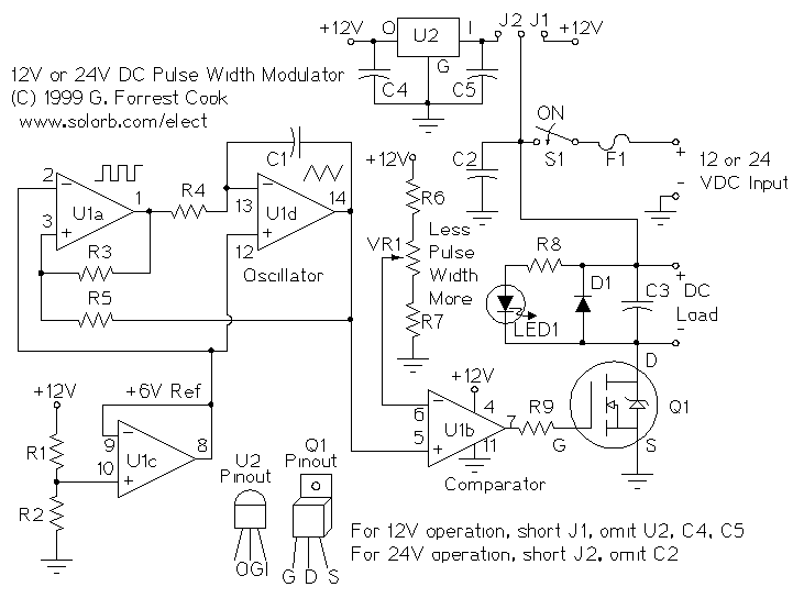
PWM is a device that can be utilized as an efficient light dimmer or DC motor speed controller. Function: for a general-purpose device that can... PWM (Pulse Width Modulation) is a versatile technique widely employed in various electronic applications, particularly...
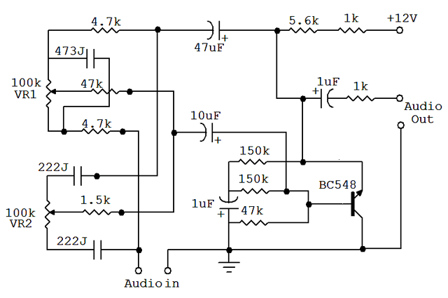
An audio equalizer circuit is utilized to modify the frequency response of an audio signal. This particular equalizer circuit is designed for adjusting the bass and treble (tone) levels of an audio amplifier. To integrate this equalizer circuit with...
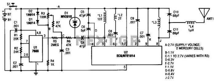
This transmitter can be utilized for multiple applications. An INS8048L microprocessor produces various codes based on keypad inputs. These codes are modulated onto a 40-kHz carrier frequency. Additionally, Q1 drives infrared LEDs LED1 and LED2. The transmitter circuit primarily consists...
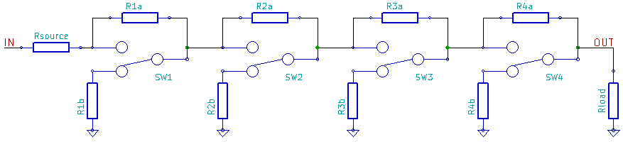
A logarithmic resistor ladder is an electronic circuit consisting of a series of resistors and switches, designed to create attenuation from an input to an output signal, where the logarithm of the attenuation ratio corresponds to a digital code...
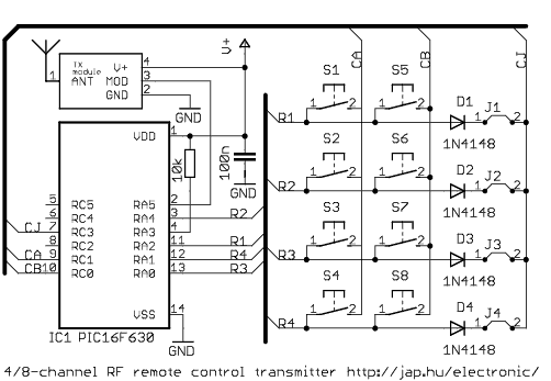
This is a general purpose remote control project with using programmable PIC microcontrollers. Schematics are shown for using infrared (RF) or radio (RF) media. If you are not familiar with microcontroller programming, you can use fixed encoder and decoder...
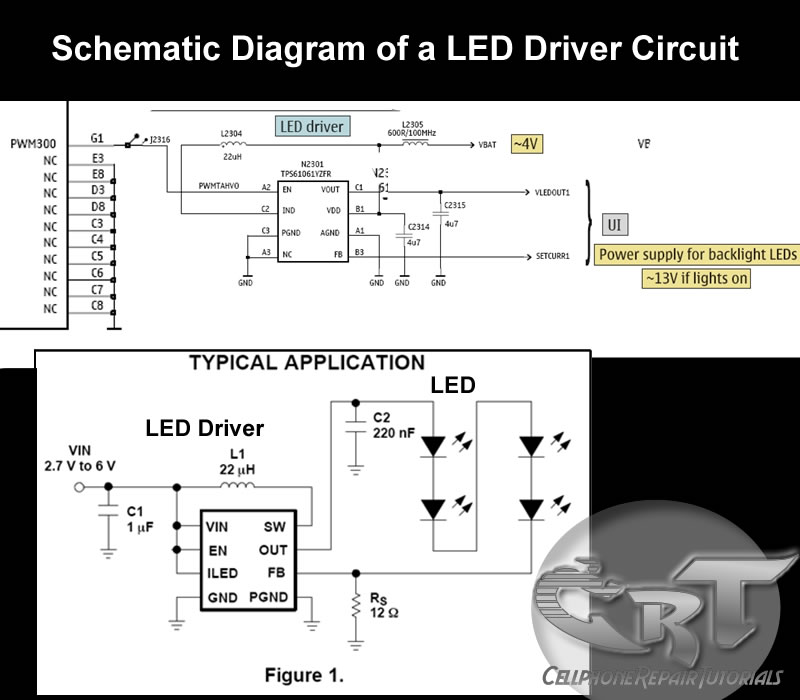
An LED (light-emitting diode) is utilized to illuminate keypad keys and LCD screen displays on all mobile phone handsets. It is controlled by the voltage or current drawn at its terminals. In the schematic diagram, the LEDs are driven...