
DC motor speed controller with 555 timer
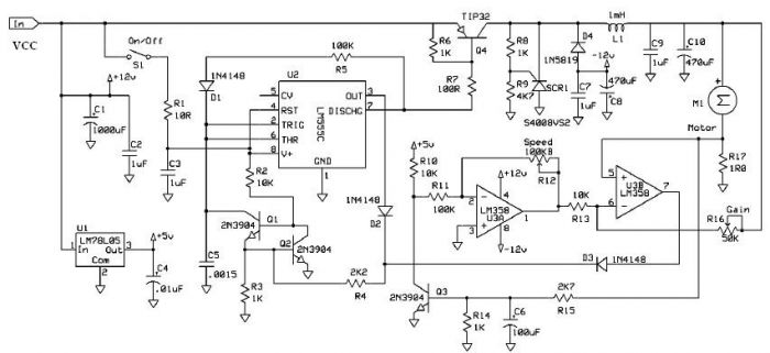
In this circuit design, speed regulation is a critical function that relies on precise feedback mechanisms to maintain optimal motor performance. The use of resistor R17 allows for effective measurement of the motor current, which is essential in compensating for any losses due to motor resistance. The gain potentiometer plays a vital role in fine-tuning the feedback loop; setting it just below the oscillation threshold ensures stable operation without introducing instability into the system.
Adjusting resistor R11 is crucial for expanding the range of speed control. This resistor can influence the feedback gain, allowing for a broader spectrum of motor speeds to be achieved while maintaining control fidelity. The careful selection of R11 can lead to improved responsiveness and stability in the motor's operation.
Transistor Q3 functions as a current limiter, protecting the circuit from excessive current that could damage components or lead to inefficient operation. This current limiting feature is essential for safeguarding the integrity of the system, especially during transient conditions or load variations.
The interaction between diode D4 and capacitor C8 is instrumental in managing the inductive kick generated by inductor L1. This inductive kick can lead to voltage spikes that may adversely affect other components in the circuit. By capturing this energy, C8 provides a stable -12 volts to operational amplifier U3, ensuring it operates within its specified voltage range. This regulation is crucial for the consistent performance of the operational amplifier, which may be involved in further signal processing or control tasks.
Finally, the role of silicon-controlled rectifier SCR1 as a flyback diode is significant in managing energy recovery in the circuit. Once C8 has absorbed the necessary energy, SCR1 prevents energy from dissipating as heat, thus enhancing overall system efficiency. This design consideration minimizes power losses and ensures that the circuit operates effectively under various load conditions.Speed regulation is accomplished by sensing the motor current with R17 and using it as positive feedback to compensate for motor resistance loss. The gain pot should be set to a point just below the point where the motor speed oscillates. After finding this point, you may want to change the value of R11 to get better speed control range. Q3 limits motor current. D4 and C8 capture some of L1`s inductive kick to produce a loosely regulated -12 volts for U3. SCR1 acts like the usual flyback diode once C8 has stored the needed energy, preventing significant power losses. 🔗 External reference
Related Circuits
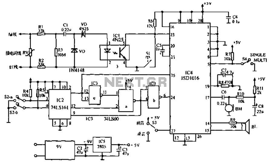
The call is made using the ISD1016 language chip for voice generation instead of a traditional phone ringing message controller schematic circuit. This controller can store messages, music, songs, or other sounds, serving as an alternative to monotonous ringing. The...
Telephone ringer utilizing 556 dual timers. This circuit generates ringing tones resembling those of a telephone by employing modulated rectangular waves of varying time periods. The telephone ringer circuit employs two 556 dual timer ICs configured to generate modulated rectangular...
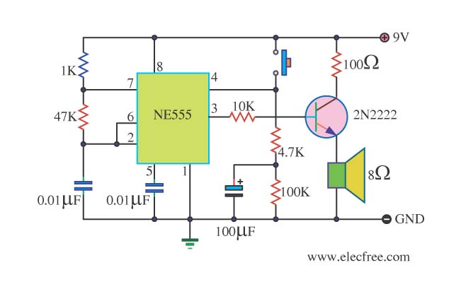
This is a danger beep circuit. It uses a 555 integrated circuit configured as a stable multivibrator that provides a duty cycle of 5% to drive a loudspeaker. The danger beep circuit utilizes the 555 timer IC, a versatile and...
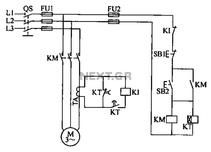
A three-phase electric motor overcurrent protection circuit. This example circuit utilizes a transformer to monitor the current, ensuring that the currents in the three-phase motor do not exceed normal operating levels. When the current exceeds the set threshold, the...
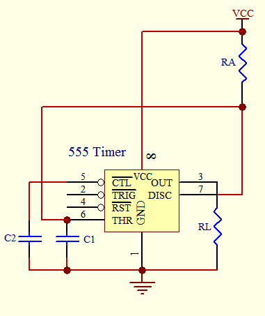
The timer circuit is utilized in various projects and is primarily categorized into two types. The first type is an analog RC circuit, where the charging of the capacitor determines the timing of the circuit. This type has a...
The LM35 Smart Heater Controller Schematic features a compact circuit designed around the well-known 3-Pin Integrated Temperature Sensor LM35 (IC1) from National Semiconductor. Additionally, a widely used BiMOS Op-amp CA3140 (IC2) is employed to monitor the temperature sensor's output,...