
converter lhc600a 40v
The power converter circuit is designed with a robust architecture to ensure reliable operation under the demanding conditions of the LHC environment. The half-bridge resonant topology allows for efficient power conversion, minimizing heat generation and improving overall system efficiency. The dual thyristor configuration enables precise control over the output voltage and current, which is crucial for maintaining the superconductive magnets at their required operational parameters.
The FGC plays a pivotal role in the system's performance, utilizing advanced algorithms for real-time current regulation. The integration of high-precision ADCs ensures that the current measurements are accurate, allowing for timely adjustments to the control loop. This level of precision is essential for preventing quenching of the superconductive magnets, which can occur due to excessive current or thermal fluctuations.
In addition to the primary functions of power delivery and current control, the safety features incorporated into the power converter are critical for the protection of both the equipment and personnel. The Fast Abort signal and the crowbar system provide multiple layers of redundancy, ensuring that any fault conditions are addressed swiftly and effectively. The design of the interlock system further enhances safety by enabling immediate response to detected faults.
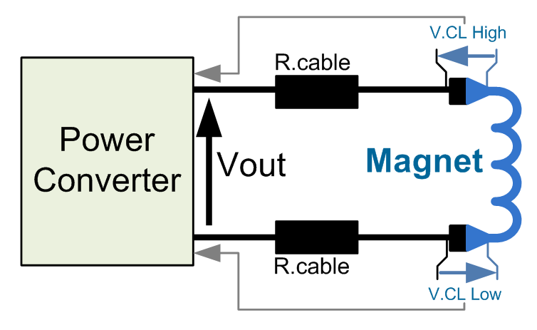
The overall design philosophy of the LHC power converter emphasizes reliability, efficiency, and safety, making it a vital component in the operation of superconductive magnets within the LHC machine. The careful consideration of both operational and safety requirements ensures that the power converter can perform effectively in the high-energy physics environment of the LHC.This Power Converter is used in LHC Machine to power superconductive magnets. It is located in the LHC underground installation, close to the loads to limit cable losses in the underground installation. Voltage Source is based on a half bridge resonnant topology (dual thyristor) followed by a 4 quadrant linear stage to allow the 4 quadrant operati
on. This topology gives a very low output EMC noise, at a cost of some control complexity given by the different stages. High precision current control loop is managed by the digital controller called FGC (Function Generator Controller).
This unit includes a high precision Sigma Delta Analog to Digital Converter which digitalize the analog current measurement coming from 2 DCCTs (DC current Transducer). Precision is then directly relying on sensor precision: DCCT, the ADCs, and the algorithm being used for the regulation loop.
Voltage source is then used as a power amplifier, powering the load through a high bandwidth voltage loop (>500Hz). Power Converter is part of magnet protection scheme, even if not directly fully responsible of the monitoring and diagnostic of the superconductive magnet status.
Dedicated systems QPS (Quench Protection System) + PIC (Power Interlock Controller) can interlock Power Converter if magnet safety requires it. LHC600A-40V Power Converter is also responsible of the current leads protection. These current leads are the 2 (minus and plus polarities) electrical conductors located at the transition between cold and warm environment.
Power Converter provide a safe incoming signal called Fast Abort. This redundant signal uses 2 paths to interlock and stop the converter and its redundancy is checked each time it acts. Magnet current path is ensured through a dedicated system called crowbar or through Power Module in case its output stage dies in short.
Crowbar active system is located in the rack and provides a safe resistive discharge path for magnet current, with a capability to dissipate, most of the time, part of magnet energy. The system is based on a 50 mOhms Power Resistance series back-to-back thyristors being fired at a given output voltage ( ±53V), and then providing a safe path for magnet current.
Additional DC-Contactor (Converter type A) ensure that no potential short-circuits at the level of the Power Module can prevent the magnet energy to be actually dissipated in the Crowbar resistance. Machine Interlock system can request a Fast Abort to the converter, in case a quench is detected. Converter is then assumed to react as soon and as quick as possible, stopping providing energy to the load.
Delay time between a Fast Abort request and actual opening of the 4-quadrant output power stage is less than 1mS, but 20ms, AC Mains Contactor delay time, should be considered as a worst case (internal control malfunction case). A typical sequence could be described as follow: This signal being part of the magnet safety scheme, it is acting redundantely at the level of Converter AC Mains Contactor.
2 paths are used and monitored to stop the contactor. Detection system is an active / passive system, since relying on a converter state-controlled 100mA current source. Active system is disabled when Power Converter is set ON, S1 being ON and short-circuiting the 100 Ohms resistor, with a 10 Ohms resistance series a fuse only being connected between negative polarity and earth.
Active system is enabled when Power Converter is set OFF. The active circuit injects a 100 mA DC current on a grounded resistive branch, resulting in a common mode voltage at the output circuit easing the earthing fault detection. Output circuit Common mode voltage is, without any earth fault, around 10V (=100 mA x 100 Ohms), and is not relying on load operation, making possible to detect an earth fault with converter being OFF.
(OFF, not condamned). If an earth fault occurs on the output circuit, a faulty current will be deviat 🔗 External reference
Related Circuits
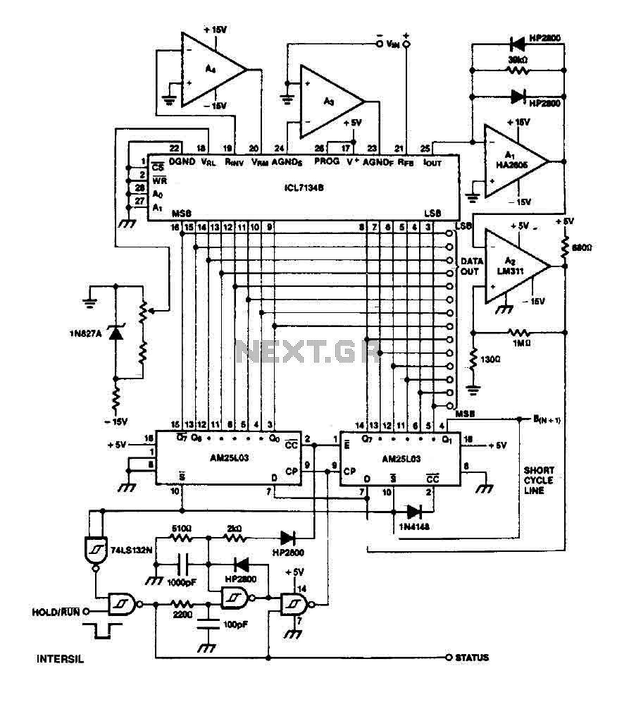
The ICL7134B circuit is a bipolar input analog-to-digital (A/D) converter that employs two AM25L03 chips to create a 14-bit successive approximation register. The comparator features a two-stage amplifier, HA2605, which is utilized to mitigate settling time issues at the...
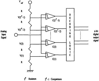
Analog-to-digital converters are categorized into one-step architectures, including flash, folding, and interpolative topologies, as well as multi-step architectures, such as successive approximation and pipeline topologies. The flash architecture is considered the fastest type of analog-to-digital converter due to its...
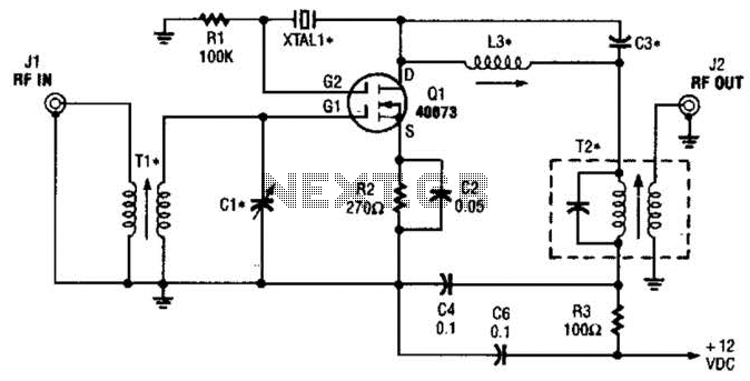
The second gate (G2) of a MOSFET can be utilized to integrate a crystal oscillator within the same stage as a frequency mixer. While this technique is common in tube technology, it is rarely implemented in dual-gate MOSFET circuits....
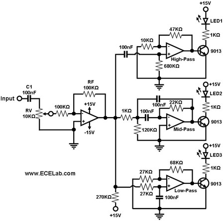
The simple circuit for converting an audio signal. The circuit basically consists of a buffer/amplifier stage and three filter circuits. The audio signal conversion circuit is designed to process audio signals efficiently while maintaining signal integrity. The circuit architecture includes...
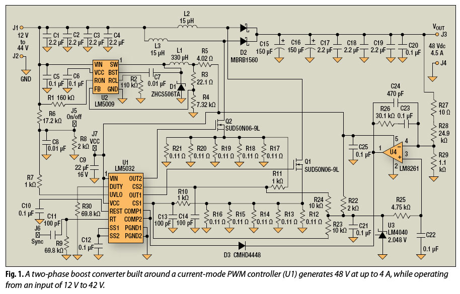
The multiphase approach has long been utilized to enhance efficiency, minimize ripple, and reduce the size of capacitors and inductors in buck converters. This method can also offer similar advantages for boost converters. The multiphase technique involves the use of...
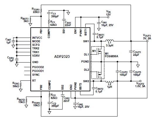
The ADP2323 DC-DC converter is designed to deliver two output voltages with specified maximum output currents. The first channel provides a 5-volt output with a maximum current of 2 Amperes, while the second channel supplies 1 volt with a...
Warning: include(partials/cookie-banner.php): Failed to open stream: Permission denied in /var/www/html/nextgr/view-circuit.php on line 713
Warning: include(): Failed opening 'partials/cookie-banner.php' for inclusion (include_path='.:/usr/share/php') in /var/www/html/nextgr/view-circuit.php on line 713