
Coolant Alarm

The coolant level alarm circuit is an essential component in maintaining the proper function of a vehicle's cooling system. The design incorporates a hall-effect sensor that detects the position of the float within the expansion tank. When the coolant level drops below a predetermined threshold, the sensor triggers an output signal. This output is fed into a delay circuit that utilizes a capacitor and variable resistors to prevent false alarms caused by temporary shifts in coolant level due to vehicle movement.
The circuit is powered by a 12V supply, with a fuse included for safety. Upon detecting low coolant, the hall-effect sensor activates a transistor that begins to charge the capacitor. The charging time is adjustable via the variable resistors, allowing the user to set the desired delay before the alarm is triggered. Once the capacitor reaches the threshold voltage of 6V, it activates a relay or transistor that powers the buzzer and LED indicator, providing both audible and visual alerts.
The third variable resistor in the circuit is crucial for controlling the discharge rate of the capacitor. This feature ensures that the system can differentiate between transient drops in coolant level and sustained low levels, allowing for accurate alarm conditions. The design is robust yet simple, making it suitable for various applications where liquid level monitoring is required.
Overall, the upgraded expansion tank and redesigned float mechanism enhance the reliability of the coolant level alarm system, reducing the likelihood of false alarms while providing critical feedback to the driver about the vehicle's cooling system status. The integration of a delay circuit further improves the functionality of the alarm, ensuring that it operates effectively under different driving conditions.My coolant level alarm has been working for the last 6 years, the alarm started to go off fairly regularly, although every time I checked the expansion tank, there was no problem with the level of coolant. Even with a cold engine, and using a screwdriver to push the float down, everything seemed okay. The problem slowly became worse, until it was triggering virtually constant, and with the noise of the buzzer in the car driving me and my wife mad, there was no option but to disconnect the thing. Luckily, by having built a fuse into the 12v supply, it was simple enough to do. Stripping the circuit board out of the car, and bench testing it with an oscilloscope, I still couldn`t find a problem, so back in the car it went for further testing.
I added an extra 12v light into the circuit, between the return wire from the hall-effect sensor and ground, so I would be able to see immediately the sensor tripped, rather than wait for the delay circuit to turn on the buzzer and the original led. However. while trying to static test it again, pushing the float down with a screwdriver, it failed to work at all.
What did happen is when I pulled out the screwdriver, there was this small 19mm long magnet stuck to the end. ! What appears to have happened is that the magnet, fitted vertically into the float, has been slowly dropping out, triggering the alarm prematurely, but each time I tested the alarm, by manually pushing the float down to the bottom of the tank, the magnet has been pushed back in, only to slowly work it`s way out again.
Since the float and magnet cannot be replaced, the only option was to purchase a new expansion tank. The float in the new tank appears to have been redesign, with the magnet or magnets being embedded in the float horizontally (not shown), though it`s very difficult to see and be sure. Also, note how the colour and nature of the float in my tank has degraded, when compared with that of the float in another old and not much used tank (see photo on the left) Since this problem is due to a failure of the float and magnet in the expansion tank, and is not directly related to the electronic alarm itself, I think that it is highly likely that it may occur with any low level alarm system on the market.
The simplest alarm would be to connect a dash mounted bulb or LED, and a buzzer, straight onto the output of the sensor that fits in the bottom of the coolant header tank. These would immediately turn on as soon as the level of coolant in the tank dropped. Driving a MGF, if one was to take a sharp turn to the left at about 20 MPH, or a gentle turn to the left at about 70 or 80 MPH, the coolant in the tank is forced to the right and the level at the sensor can drop.
This would then turn the light & buzzer on briefly, until the level of the coolant returned to normal. With a lot of turning, these false triggers would become very annoying. The idea of my circuit is to delay turning on the light and the buzzer for a number of seconds so that you are then certain of a true alarm.
When the sensor detects low coolant, it starts to charge up a capacitor, and when that charge reaches 6v, the light and buzzer are turned on. The length of time it takes to reach that point is controlled by the 2 variable resistors that sit side by side in the circuit, and adjustment can vary the time from very small delay, to up to about 9 or 10 seconds.
Mine is set around 6 seconds. When the sensor detects that the coolant level has returned to normal, the third variable resistor controls how quickly the capacitor charge decays before turning off the light and buzzer. The idea is that should the sensor detect rapid and consecutive falls and rises of the coolant, the charge in the capacitor would still build up ( bit like a saw tooth pattern ) and eventually trip the alarm.
I purchased and fitted the new expansion tank, Part Number PCF000141 - perhaps 🔗 External reference
Related Circuits
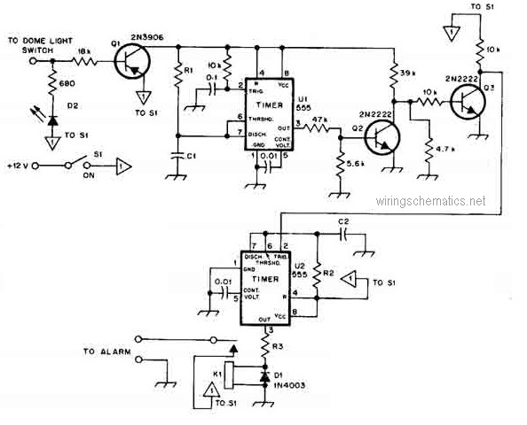
This circuit diagram represents a smart car alarm timer. This design is more advanced compared to traditional car alarm systems. When activated, the alarm remains active for 80 seconds, following an initial delay of 15 seconds. The smart car alarm...
With the fast-paced nature of modern life, the frequency of traffic accidents is also increasing. To enhance vehicle safety, this text presents a mechanically controlled car anti-collision alarm system designed as a single unit. This device integrates real-time control...
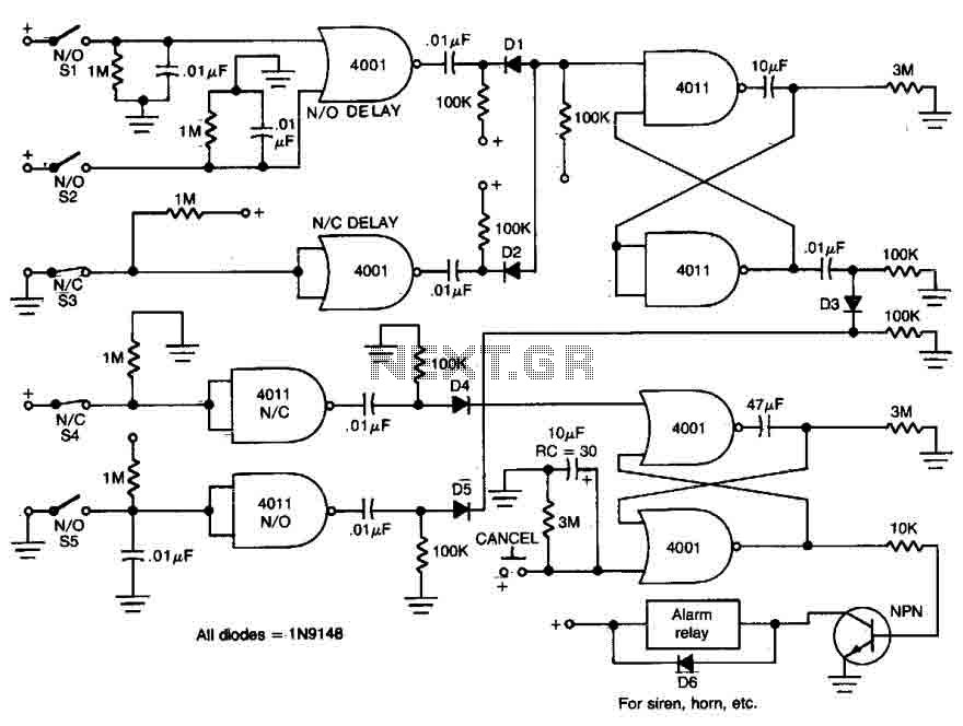
This circuit features open and closed loop contacts (switches 1, 2, 3) that activate the alarm, which remains on for a duration of 5 to 10 minutes. The triggering delay for entrance and exit is set to 27 seconds....
The CD4538 is a precision monoflop available in DIP-16 and SMD-16 packages. It offers stable performance with fewer required external components and strong logic functionality. The chip integrates two independent single-shot circuits, making it widely applicable in counting, division,...
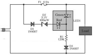
This circuit is designed to monitor the performance of the equipment. It includes a fuse check feature. The circuit is compact and can operate with various power supply voltages. It utilizes a two-color LED, which is of the common...
This circuit activates an alarm whenever an object crosses the laser beam emitted by a laser. The output of the IC TL071 goes high when the laser beam is interrupted. This output voltage is further amplified by an NPN...