Design on the basis of AT89C2051 intelligent automobile anticollision alarm equipment
18,241
With the fast-paced nature of modern life, the frequency of traffic accidents is also increasing. To enhance vehicle safety, this text presents a mechanically controlled car anti-collision alarm system designed as a single unit. This device integrates real-time control and data processing capabilities of a microcontroller with ultrasonic range-finding technology and sensor techniques. It can measure the distance and speed between a vehicle and obstacles behind it while in motion, displaying the distance on a digital display and providing audible warnings based on the distance detected. The principle of ultrasonic range finding involves emitting ultrasonic waves, which reflect off obstacles and return. By measuring the time difference (T) of the returning waves, the distance (S) can be calculated using the formula S = C * T/2, where C is the speed of sound in air (approximately 344 m/s at room temperature). Once the speed of sound is established, measuring the round-trip time of the ultrasonic waves allows for accurate distance determination. Vehicle speed measurement is accomplished using a Hall effect integrated sensor. This sensor is connected to a rotary table attached to the vehicle's wheel axle. As the wheel rotates, the permanent magnet on the rotary table passes the Hall sensor, generating a magnetic signal at the sensor's input. Continuous rotation of the rotary table enables the Hall sensor to output a rotational speed signal, effectively measuring the frequency of that signal. The AT89C2051 is a low-power, high-performance CMOS microprocessor compatible with the MCS-51 instruction set and pin configuration. It features 2KB of RAM, 15 I/O pins, two 16-bit timers/counters, five interrupt sources, a full-duplex serial port with 128 bytes of memory, an accurate analog comparator, and an on-chip oscillator, all while maintaining low power consumption in standby and power-down modes. The operating voltage range is 4.25V to 5.5V, with a maximum operating frequency of 12MHz. The two 16-bit timers (T0 and T1) in the AT89C2051 operate at a machine cycle rate of 1/12 of the oscillator frequency for timer functions, and can count changes on external input pins P3.4/T0 and P3.5/T1 at a rate of 1/24 of the oscillator frequency for counter functions. The control system includes the ultrasonic transmitting circuit, receiving circuit, speed measurement circuit, alarm circuit, and LED display circuit, forming the complete alarm system. The functional block diagram of the circuit is depicted in Fig. 1. The ultrasonic transmitting circuit is composed of a CC7555 timer circuit and ultrasonic wave generator. The P1.7 pin of the AT89C2051 controls the CC7555 timer circuit to produce a 40kHz frequency signal for the ultrasonic generator, which emits ultrasonic waves that penetrate and reflect off obstacles. The ultrasonic range-finding system is characterized by high sensitivity, strong penetration, rapid measurement, and the ability to gauge larger range objects effectively. The ultrasonic receiving circuit includes a probe, amplifier, and reshaper. The reflected ultrasonic waves are captured by the receiving probe, converted into an electrical pulse signal, and sent to the AT89C2051 via the P3.2 pin after amplification and reshaping. The amplifier must be selected to ensure a sufficient gain-to-noise temperature ratio and low noise broadband amplification for optimal performance.With the quickening of the modern rhythm of life, the frequency happening in traffic accident is increasing too, in order to improve the safety that the car runs, this text introduces the mechanically controlled car anticollision alarm system of a one piece. This device combines real time control and data processing function of the one-chip comput er with ultrasonic range finding technology, sensor technique, can measure the car in distance and car speed between rear obstacle and car while running, reveal the distance through the digital display device, and is given out the warnings according to the distance situation by the voicing circuit. The principle of ultrasonic range finding is, launch, meet the obstacle reflected back wave through measuring supersonic wave constantly, thus measure and launch supersonic wave and receive the time difference T of the back wave, then find the distance S =C * T/2, among them, C is the ultrasonic wave speed, it is 344m/s to fetch at room temperature.
After the velocity of sound is confirmed, so long as measure supersonic wave for round time, can try to get the distance. The measurement of the car speed is realized by Hall`s integrated sensor. Namely, link the input shaft equipped with rotary table of the permanent magnnet with the axis of rotation of the wheel, when the wheel rotates, the rotary table is thereupon turning, at this moment, the permanent magnnet on the rotary table will pass Hall`s integrated sensor, thus get a magnetic signal in the input end of Hall`s integrated sensor, rotate if rotary table ceaselessly, Hall integrated sensor can output rotational speed signal.
We can say, the measurement of the car speed is actually the measurement of the frequency to the rotational speed signal. AT89C2051 is a low power consumption, high-performance CMOS8 location microprocessor, compatible with MCS-51 series instruction sets and pins, have the following characteristics: RAM, 2Kbytes EPROM, 15 I/O threads, 2 16 timing / counter, 5 two-step interrupt sources, a full duplex serial port within 128 bytes, an accurate analog comparator and one slice of internal oscillators on-chip, low power consumption stand-by and power down mode.
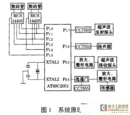
Job voltage range 4. 25V- 5. 5V, operating frequency fetches 12MHz. Two 16 timing / register T0 and T1 in AT89C2051, while making the timer, the machine cycle of isarithmic, it is 1/12 of the oscillating frequency to count the frequency; While functioning as the counter, can be to increasing by 1 when present the change from 1 to 0 on the pin P3. 4/T0 and P3. 5/T1 of external input, it is 1/24 of the oscillating frequency to count the frequency. Until control system, ultrasonic transmitting circuit, receiving circuit, test the speed circuit, alarm circuit, LED display circuit make up alarm equipment this, the functional block diagram of the circuit is shown in Fig.
1. The ultrasonic transmitting circuit is launched the probe to make up by CC7555 time base circuit and supersonic wave. P1. 7 pin of the one-chip computer AT89C2051 controls CC7555 time base circuit to produce the frequency signal of 40kHz for the ultrasonic generator, the supersonic wave visited the hair by supersonic wave and penetrated sends out the obstacle.
Utilize ultrasonic range finding to have the following characteristics: Measure the high sensitivity, penetrating power is strong, measurement is fast, it is great to measure the angle, can gauge inner object of larger range. The ultrasonic receiving circuit is received the probe, amplifier and reshaper to make up by supersonic wave.
The supersonic wave reflected back by the obstacle, through receiving the probe, transform to the electric pulse signal, P3. 2 pin sent into the one-chip computer AT89C2051 after being and then amplified and had a facelift by the amplifier, reshaper.
The amplifier should choose enough gain to noise temperature ratio and more low-noise broadband amplifi 🔗 External reference
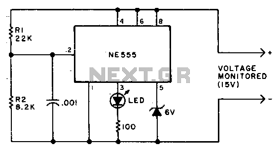
Due to the low duty cycle of the flashing LED, the average current drain is 1 mA or less. The NE555 will trigger the LED when the monitored voltage falls to 12 volts. The ratio of R1 to R2...
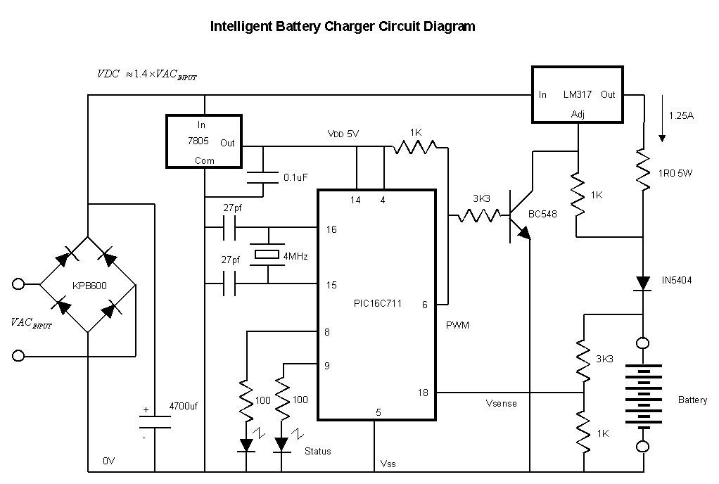
This affordable and simple-to-construct NiCd/NiMH battery charger is designed for the automatic charging of various batteries used in numerous applications. Reliable chargers are typically costly, while inexpensive chargers that come with original equipment often fail to charge cells correctly,...
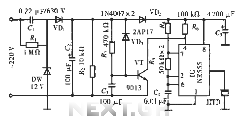
The circuit utilizes a 555 integrated circuit (IC). When an incoming call is received, 220 V AC is stepped down through resistor R1, followed by rectification using diode VD1. A voltage regulator (DW) is employed, and capacitor C2 is...
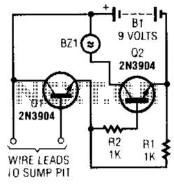
A common collector amplifier drives a 2N3904 switch to sound alarm BZ1. The wire leads to a water sensor or sump pit, level switch, etc. It is used to allow the alarm to operate and be mounted in a...
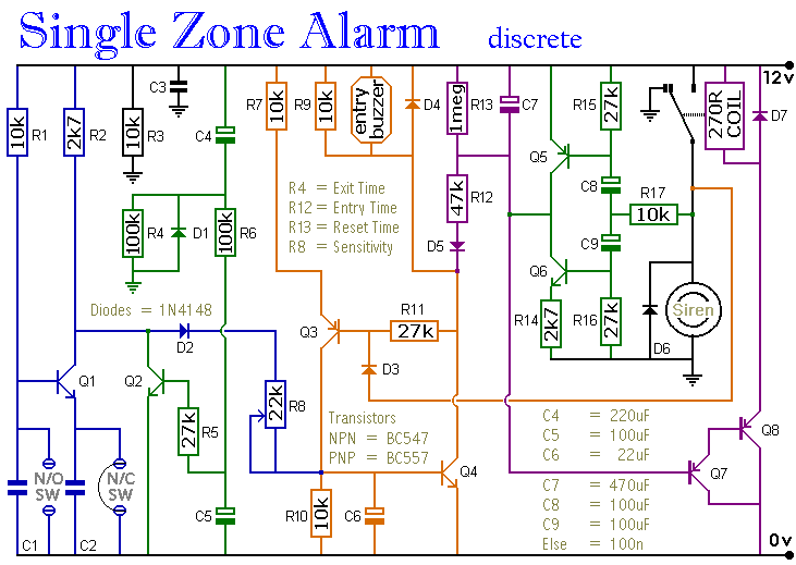
A single zone alarm circuit with entry and exit delay and other facilities. The circuit features automatic exit and entry delays, timed bell cut-off and system reset. It has provision for normally open and normally closed switches and will...
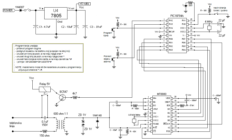
Connect this Alarm Phone Dialer to a device you wish to monitor, such as a high water alarm, low temperature alarm, back window, or garage door. When activated, it will call a series of pre-programmed numbers to notify you...
We use cookies to enhance your experience, analyze traffic, and serve personalized ads.
By clicking "Accept", you agree to our use of cookies.
Learn more