
Coop automatic controller circuit diagram

The power circuit comprises a power transformer (T), a rectifier bridge (UR1), an LED (HL), a three-terminal integrated voltage regulator (IC), and a filter capacitor (C1). The humidity detection circuit includes a humidity control resistor (RS), a rectifier bridge (UR2), a potentiometer (RP1), transistors (V1, V2), diodes (VD1, VD2), resistors (R1 to R4), a capacitor (C2), and a relay (K1). The light detection control circuit is made up of a phototransistor (V3), transistors (V4, V5), resistors (R5 to R8), a potentiometer (RP2), diodes (VD3, VD4), and a relay (K2). The temperature detection control circuit consists of a thermistor (RT), resistors (R9 to R12), transistors (V6, V7), a capacitor (C4), a potentiometer (RP3), and diodes (VD5, VD6), along with a relay (K3).
The AC 220V voltage is transformed by T, generating AC voltages of 15V and 6V on windings W2 and W3, respectively. The 15V AC is rectified by UR1, regulated by the IC, and filtered by C1 to provide a stable 12V DC voltage. The 6V AC voltage is stepped down and rectified via UR2, with RP1 connected to two fixed ends. When humidity is insufficient, the high resistance of RS causes a drop in the base voltage of V1, leading to the conduction of V2 and activation of K1, which connects the humidifier to the power supply. When humidity levels reach the desired range (55% to 65% relative humidity), the resistance of RS decreases, turning off V1 and V2, thus deactivating K1 and stopping the humidifier.
In terms of light control, when sufficient light is present, the internal resistance of phototransistor V3 decreases, causing V4 and V5 to turn off, which releases K2 and turns off the fill light. Conversely, when light levels are low, the resistance of V3 increases, leading to the conduction of V4 and V5, activating K2 and illuminating the fill light. For temperature regulation, when the temperature is within the optimal range (15°C to 25°C), the resistance of thermistor RT decreases, resulting in the closure of V6 and V7, which keeps K3 deactivated and the heating device off. If the temperature drops below the desired level, the resistance of RT increases, causing V6 and V7 to conduct, which activates K3 and powers the heating system. Once the temperature reaches the specified level, V6 and V7 turn off, releasing K3 and stopping the heating device.
For component selection, resistors (R1 to R12) should be 1/4W carbon film or metal film types. The thermistor (RT) should be an MF11 type negative temperature coefficient thermistor, while the humidity sensor (RS) should be an MS01-A type humidity-sensitive resistor. Potentiometers (RP1 to RP3) are made from organic solid materials. Capacitors (C1 to C4) should be 25V aluminum electrolytic types. Diodes VD1, VD3, and VD5 are 1N4148 silicon switching diodes, while VD2, VD4, and VD6 are silicon rectifier diodes. Bridge rectifiers UR1 and UR2 are rated for 1A at 50V. Transistors V1, V4, and V6 can be 3DG6 or 59013 models, while V3 is a 3DU5 phototransistor, and V2, V5, and V7 can be 3DG12 or C8050 types. The voltage regulator IC can be an LM7812 or CW7812 model, and relays K1 to K3 should be JRX-4 type 12V DC relays. The transformer (T) should be rated for 5 to 8W with secondary voltages of 15V and 6V, and the indicator LED (HL) can be 6.3V.Coop automatic controller described in this case, capable of sheds light, temperature and humidity automatically adjusted to increase egg production rate and survival rate of c hickens. The device for use chicken specialized households in rural areas. Circuit works The house automation controller circuit from the power circuit, the humidity detection control circuit, lighting and temperature detection control circuit detecting control circuit, as shown in FIG. Power circuit from the power transformer T, rectifier bridge pile UR1, LED HL, three-terminal integrated voltage regulator IC and filter capacitor C1.
Humidity detection by the humidity control circuit resistor RS, rectifier bridge pile UR2, potentiometer RP1, transistor V1, V2, diode VD1, VD2, resistors R1 ~ R4, capacitor C2 and the composition of the relay K1. Light detection control circuit by the phototransistor V3, transistor V4, V5, resistor R5 ~ R8, potentiometer RP2, diode VD3, VD4 and relay K2 components.
Temperature detection control circuit by the thermistor RT, resistor R9 ~ R12, transistor V6, V7, capacitor C4, potentiometer RP3, diodes VD5, VD6 and relay K3 composition. AC 220V voltage by T Buck, respectively, generates an AC voltage and AC 15V 6V voltage on the winding W2 and W3 winding.
15V rectified AC voltage by UR1, IC voltage regulator and C1 filtered for the whole provide 12V DC voltage; the AC 6V voltage via an RS-limiting step-down and UR2 rectified, added to the RP1 two fixed ends. When the humidity inside the house is not enough, the resistor RS humidity resistance is large, so that the base voltage V1 due to decrease end, V2 conduction, K1 pull its normally open contact connected to the power supply of the humidifier, humidifier humidification spray.
When the humidity inside the house to meet the requirements (relative humidity 55% ~ 65%), RS resistance becomes smaller, so that conduction V1: V2 off, K1 release, the humidifier stops working. When adequate light in the house, phototransistor V3 internal resistance becomes smaller, so that V4 and V5 off, K2 is released, fill light does not shine.
When there is insufficient light inside the house, V3 internal resistance becomes larger, so that V4 and V5 conduction, K2 pull its normally open contact connected, fill light is lit. In the house temperature suitable (15 ~ 25 ), the thermistor resistance RT smaller, V6 and V7 are closed, K3 does not pull, the heating device does not work.
If the low temperature inside the chicken coop, the RT resistance becomes larger, so that V6 and V7 conduction, K3 pull its normally open contact connected to the power supply of the heating means, to start with heating. When the temperature reaches the required temperature inside the house, V6 and V7 off, K3 release, the heating device stops working.
Component selection R ~ 812 select 1/4W carbon film resistors or metal film resistors. RT use MF11 type negative temperature coefficient thermistor. RS selection MS01-A type humidity sensitive resistor. RP1 ~ RP3 are made of organic solid potentiometer. C1 ~ C4 are selected voltage is 25V aluminum electrolytic capacitors. VD1, VD3 and VD5 are made of 1N4148 silicon switch diode; VD2, VD4 and VD6 are made of silicon rectifier diode. UR1 and UR2 are selected bridge rectifier 1A, 50V of. V1, V4 and y6 are selected 3DG6 or 59013,3DG9013 silicon NPN transistor; V3 selection 3DU5 type phototransistor; V2, V5 and V7 are selected 3DG12 or Model C8050 silicon NPN transistor.
IC selects LM7812 or CW7812 type three end steady voltage integrated circuits. K1 ~ K3 are selected JRX-4 type 12V DC relay. T optional 5 ~ 8W, secondary voltage of 15V and 6V power transformer. HL optional 6.3V indicator.
Related Circuits
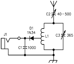
A crystal radio receiver is a very simple radio receiver that requires no battery or external power source, operating solely on the energy harvested from radio waves through a long antenna. A crystal radio receiver is a passive radio receiver...
An NE592 or LM733 is utilized as a general-purpose video amplifier in this schematic. J2 and J3 deliver two anti-phase outputs. R2 functions as a gain control. The bandwidth is approximately 100 MHz. The NE592 and LM733 are integrated circuits...
LCD initializations in 8051 C programming involve understanding the logic behind serial communication, including the duration of SIG pulse transmission and the necessary delays. These statements inform the compiler that a 16x2 LCD is connected to the defined pins...
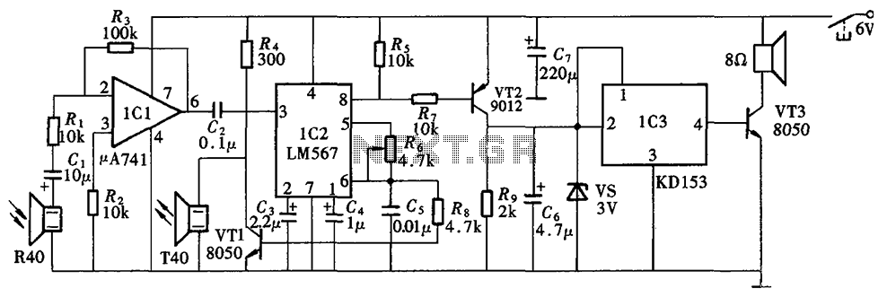
The Blind Pathfinder circuit primarily consists of the A741 operational amplifier, LM567 phase-locked loop, KD153 transistor, 8050 transistor, 9012 transistor, and various other components. The Blind Pathfinder circuit is designed to assist in navigation and obstacle detection, typically utilized in...

The Dodge Aspen was a compact car produced from 1976 to 1980 by Chrysler Corporation's Dodge division. The 1976 Aspen model year was available as a 2-door coupe, 4-door sedan, or 4-door station wagon, and it came in three...
The crime prevention bell device produced approximately 20 years ago remains in active service. It has effectively deterred thieves on multiple occasions by triggering an alarm as they attempt to enter. The bell continues to ring, functioning as a...