
In-Car lights delay circuit

The circuit operates by utilizing a timing mechanism based on an RC (resistor-capacitor) network. The 10kΩ resistor and the 4.7MΩ resistor are connected in series with a capacitor, forming a delay circuit that controls the charging and discharging time. When the circuit is powered, the capacitor begins to charge through the resistors, and the voltage across the capacitor increases gradually. Once the voltage reaches a certain threshold, it triggers a transistor or a relay that activates the internal lights.
To adjust the delay time, the values of the resistors and the capacitor can be modified. Increasing the capacitance or the resistance will result in a longer delay, as it takes more time for the capacitor to charge to the threshold voltage. Conversely, decreasing these values will shorten the delay time.
The circuit can be powered by the car's battery, ensuring that it operates effectively when the vehicle is in use. Additionally, it is essential to include protection components such as diodes to prevent reverse polarity and protect the circuit from voltage spikes.
In summary, this circuit provides a practical solution for controlling the internal lighting of a vehicle with adjustable timing, enhancing user convenience and safety. Proper selection of components and configurations will ensure reliable performance in automotive applications.This circuit switch slowly on and off the internal lights in a car. The delaying time can be adjusted changing the values of the 10k, 4M7 resistors and capacitor. Source: NEXT. GR 🔗 External reference
Related Circuits
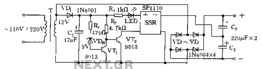
The circuit is automatically converted to a low-voltage configuration. A 220V AC supply is stepped down by transformer T. After this, the breakdown voltage of diode VDw causes transistors VT1 and VT2 to turn off, resulting in the solid-state...
The following circuit illustrates a simple stepper motor controller circuit diagram. This circuit is based on the 7404 integrated circuit. Features include suitable heat dissipation. The simple stepper motor controller circuit utilizes the 7404 hex inverter IC to control the...
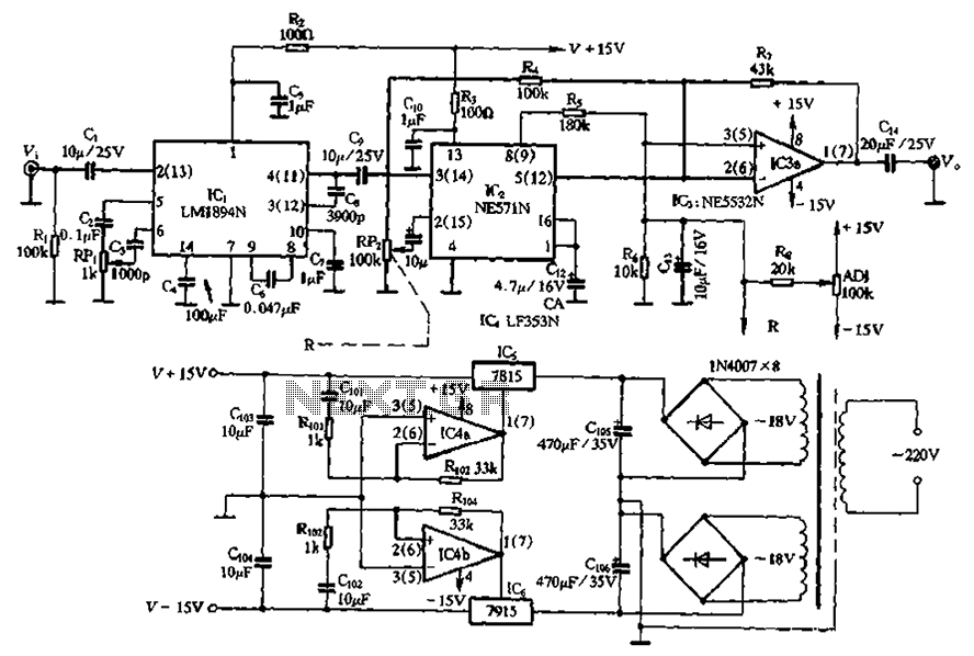
The NE571 and LM1894N form a dynamic expander circuit that enhances performance. This dynamic expander utilizes a variable bandpass filter with the LM1894N. It is particularly effective for dynamic expansion, requiring an RMS rectifier to mitigate noise modulation effects,...
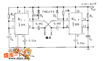
The circuit consists of two synchronized multivibrators formed by a pair of 555 timer circuits. It is capable of generating two synchronized pulse signals, with the spacing and frequency adjustable by modifying the time constant. The circuit offers flexibility...
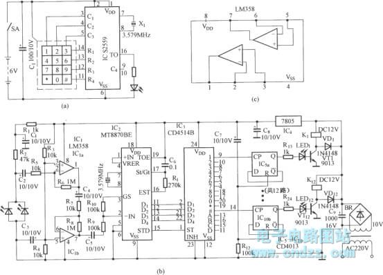
Figure (a) illustrates an infrared emission circuit composed of a 12-key keyboard and an S2559. Figure (b) displays a DTMF decoder circuit along with a channel control circuit utilizing the MT8870. Figure (c) presents a voltage amplifier circuit constructed...
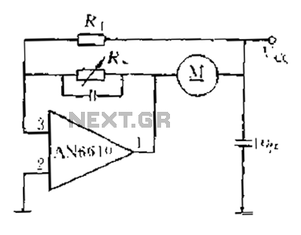
AN6610 Application Circuit operates as follows: When the supply voltage (Vcc) changes due to mechanical load variations, it can affect the motor speed. The motor speed is proportional to the back electromotive force (EMF). Consequently, the voltage across the...