
A frequency multiplier in depth
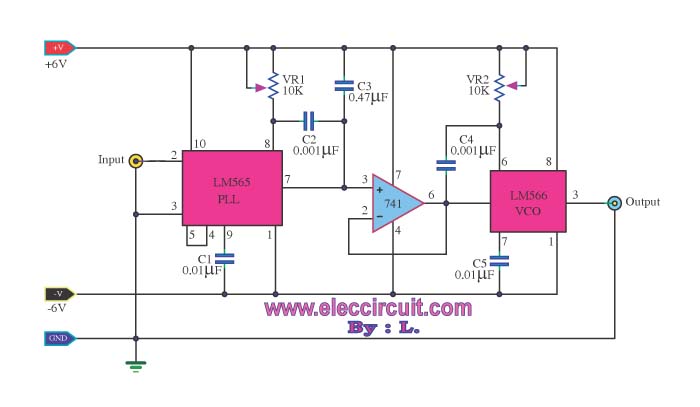
Frequency multiplier circuits are essential in various applications where signal frequency needs to be increased for better performance or functionality. The phase-locked loop (PLL) is a fundamental component in these circuits, as it synchronizes the output frequency to a reference frequency input.
In this specific frequency doubling circuit, the PLL is configured to achieve a multiplication factor of two. The core components include a voltage-controlled oscillator (VCO), a phase comparator, and a loop filter. The VCO generates a frequency that is controlled by the input signal. The phase comparator compares the phase of the input signal with the VCO output and generates an error signal that drives the loop filter. The loop filter smooths this error signal to provide a stable control voltage to the VCO, ensuring that the output frequency is precisely double that of the input frequency.
The circuit design may also incorporate additional features such as frequency stability enhancements, noise reduction techniques, and output buffering to ensure the doubled frequency signal maintains integrity across various loads and conditions. Proper layout considerations, including minimizing parasitic capacitance and inductance, are crucial in achieving optimal performance in high-frequency applications.
This frequency doubling circuit using a PLL is widely applicable in communication systems, RF transmission, and signal processing where precise frequency control is paramount.Most of the frequency multiplier circuit using IC phase locked loop (PLL).It will increase the frequency to an integer only. But this circuit can double the.. 🔗 External reference
Related Circuits
The high-frequency signal generator is designed to produce a low frequency of 1 kHz, an intermediate frequency (IF) signal of 465 kHz, and high frequencies ranging from 525 kHz to 1605 kHz. This device is particularly useful for radio...
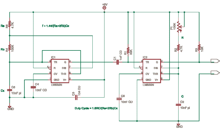
This circuit is based on an older application note from Exar. In this design, the frequency is determined by IC1, while IC2 and potentiometer P1 control the duty cycle. It is necessary to calculate the resistor (R) and capacitor...
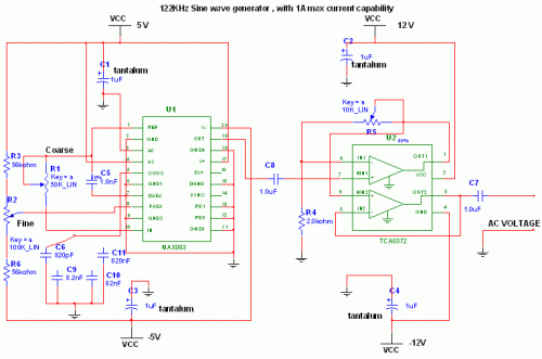
This circuit utilizes the versatile MAX038 function generator. While some advanced features of this IC are disabled in this configuration, it can still generate sine, triangle, and square waves by adjusting the A0 and A1 pins (refer to the...
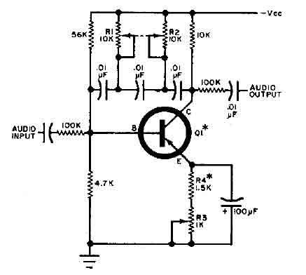
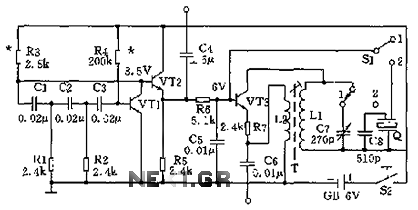
This circuit is designed for selective tuning adjustments between two closely spaced audio tones. The frequency is determined by the values of the capacitors and resistors in the feedback circuit connecting the collector and base of transistor Q1. With...
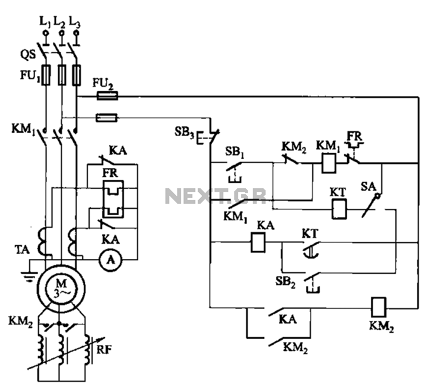
The circuit shown in Figure 3-164 can operate in both manual and automatic modes. During startup, the normally closed contact of relay KA is shorted, which affects the heating element to avoid prolonged startup times that could lead to...
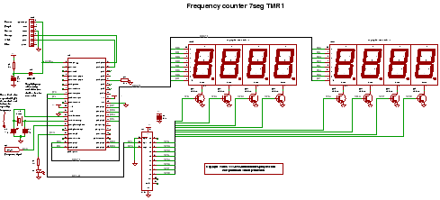
C code for a frequency counter circuit operating up to approximately 50 MHz, utilizing a multiplexed seven-segment display and employing Timer 1 to count the edges of the input signal. The frequency counter circuit described operates effectively within the range...