
Crystal Oscillator
A 10 MHz crystal oscillator circuit can serve as an effective calibration tool for frequency counters in oscilloscopes. The circuit typically consists of a crystal, a few passive components, and an operational amplifier or a transistor configured as an oscillator. The crystal serves as the frequency-determining element, while the operational amplifier or transistor amplifies the oscillation to a usable signal level.
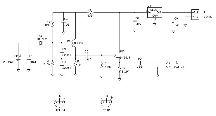
To build a simple 10 MHz crystal oscillator, a fundamental circuit design includes a quartz crystal rated for 10 MHz, a capacitor (C1) connected in parallel with the crystal to stabilize the oscillation, and a feedback resistor (R1) to provide the necessary gain. An additional capacitor (C2) can be included in the circuit for fine-tuning the frequency output. The output of the oscillator can be connected to a frequency counter or a shortwave receiver for calibration purposes.
When tuning the oscillator, the shortwave receiver should be set to the WWV frequency of 10 MHz. By adjusting capacitor C2, the oscillator can be fine-tuned until a zero-beat condition is achieved, where the tone generated by the oscillator matches the tone from the WWV signal. This method provides a straightforward way to confirm the accuracy of frequency counters in oscilloscopes, ensuring that they are properly calibrated for precise measurements.
In conclusion, constructing a simple 10 MHz crystal oscillator can be a valuable project for verifying the calibration of frequency counters in oscilloscopes. This approach not only aids in ensuring measurement accuracy but also enhances understanding of oscillator design and operation.I currently have three: a really old optoelectronics Opto-7000 which I don`t use much, a newer Mitronics MIC-1028, and my most recent acquisition, a used Tektronics 2236 `scope purchased at Dayton 2009, which has a very handy frequency counter built-in. I was working on a recent project and found the Tektronics and theMitronics counters were annoyingly out ofagreement.
How to check the calibration So I built this 10 MHz crystal oscillator. There are a lot of crystal oscillator circuits if you search the internet, some of them amazingly complex. I wanted one that was simple, had no tuned circuits, and could be tweaked to get it on frequency. I use my shortwave receiver tuned to WWV at 10 MHz. I adjust C2 to zero-beat with WWV. This can most easily be heard when the tones are present, since mis-tuning makes the tones sound wierd.
Once zero-beat, the frequency counter should read 10 MHz too. I found my Tektronics was spot on, and theMitronics needed adjustment, which was easy to do since the calibration trimmer was accessible through a small hole in the front panel. Since completing this project, I came across an interesting article on how to calibrate a counter (that has an internal 10MHz oscillator) without any extra gear (besides a receiver for WWV).
Have a look at VE2ZAZ`s blog. It doesn`t work with my Mitronics counter, though, so it must use a different reference oscillator frequency. 🔗 External reference
Related Circuits
Adapting a failed Tesla coil into a crystal radio set for demonstration purposes has presented challenges, particularly with antenna size for optimal signal reception. It has been noted that an ideal AM antenna should range between 100 to 500...
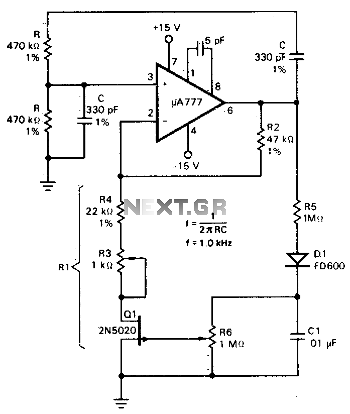
A field effect transistor (FET), designated as Q1, functions within the linear resistive region to facilitate automatic gain control. The attenuation of the RC network is one-third at the oscillation frequency with zero phase shift, necessitating that the amplifier...
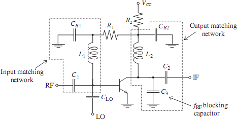
The emergence of modern radio and radar systems has created a demand for stable harmonic oscillations at specific carrier frequencies to facilitate the necessary modulation and mixing conditions. While early carrier frequencies primarily operated in the low to mid...
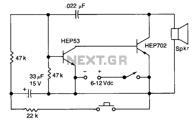
Closing the pushbutton switch initiates the siren, which then increases to a higher frequency. Releasing the switch causes the tone to decrease until switch S2 is closed again. The quality of the tone can be modified by altering the...
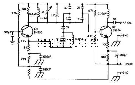
This oscillator circuit utilizes a 5th overtone crystal operating within the 85 to 106 MHz frequency range. The component Y1 represents the crystal. The circuit was initially designed for frequency control in a microwave oscillator. The oscillator circuit leveraging a...
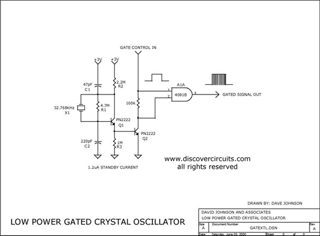
The circuit controls the output of a continuously operating 32KHz crystal oscillator, directing it to the input of a C-MOS buffer when clock pulses are required. This technique addresses the issue of a slow-starting crystal oscillator by maintaining the...