
Crystal Tester
A quartz crystal tester is an essential tool for evaluating the condition of quartz crystals, which are widely used in electronic circuits for frequency stabilization and timing applications. The tester typically operates by applying a small voltage to the crystal and measuring its response. If the crystal is functioning properly, it will resonate at its specified frequency, which can be detected by the tester.
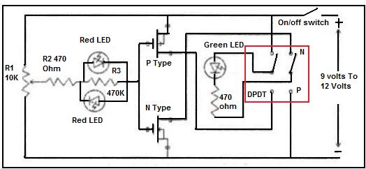
The LED light indicator serves as a visual confirmation of the crystal's status. When the crystal is good, the LED will illuminate, signaling that the crystal is operational. Conversely, if the LED does not light up, it indicates that the crystal may be broken or defective.
The circuit design of a quartz crystal tester generally includes a power supply, an oscillator circuit, and a detection mechanism. The oscillator circuit is responsible for generating the signal that is applied to the crystal. Common oscillator configurations include Colpitts and Pierce oscillators, which are suitable for testing crystals across different frequency ranges.
In addition to the LED indicator, some quartz crystal testers may also incorporate additional features such as a frequency counter or a multimeter function, allowing for more detailed analysis of the crystal's performance. This versatility makes the quartz crystal tester a valuable instrument for electronics engineers, hobbyists, and technicians involved in circuit design and repair.
Proper calibration and handling of the quartz crystal tester are crucial to ensure accurate readings and to prevent damage to the crystals being tested. Regular maintenance of the tester itself is also recommended to ensure reliability and longevity of the device.Quartz crystal tester is needed if you want to know whether the crystal is good or bad (broken). This crystal tester gives LED light indicator. If the.. 🔗 External reference
Related Circuits
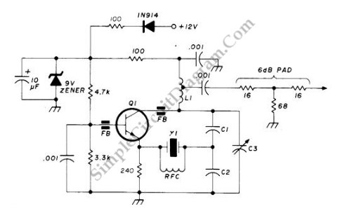
This circuit operates at a frequency range of 90-125 MHz and is particularly useful for VHF/UHF converters. It provides an output power of 5 to 15 mW. The circuit can utilize high-quality fifth- or seventh-over-tone crystal types. A ferrite...
This is a simple Colpitts crystal oscillator for 1 to 20 MHz, which can be easily constructed from spare parts, provided that a crystal is available. The Colpitts oscillator is a type of electronic oscillator that utilizes a combination of...
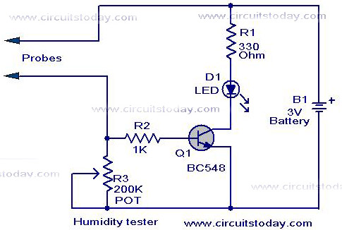
A simple humidity tester circuit using only an LED, a transistor, and a few resistors is explained with a clear circuit schematic. The humidity tester circuit is designed to provide a visual indication of humidity levels using basic electronic components....
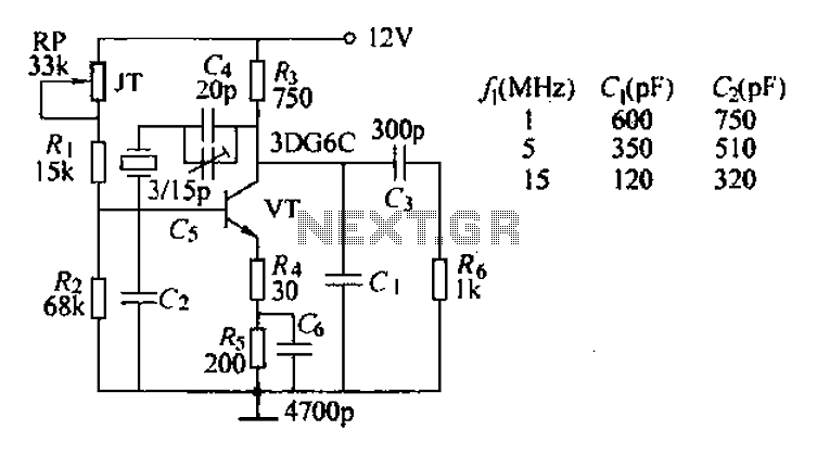
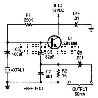
The typical crystal oscillator circuit depicted in the figure is a three-point oscillator designed for capacitance feedback. The oscillator's frequency is influenced by the series and parallel resonant frequencies of the crystal. This type of circuit is commonly known...
Field-effect transistors (FETs) are integral components found in various applications such as power sections, LCD inverters, uninterruptible power supplies (UPS), amplifiers, monitor B+ circuits, and ATX power supplies. When a FET fails, it is essential to use a meter...
Use this circuit to test if the light coming from your 40kHz IR emitter is really emitting the right frequency. The schematic says to use a GP1U5X IR module, but probably any 40kHz detector module will work. I used...