
40khz IR tester
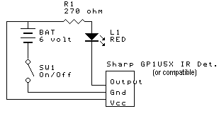
This circuit serves as a frequency tester for infrared (IR) emitters operating at 40kHz, which is commonly used in remote control systems and other IR communication applications. The primary component of the circuit is the IR detector module, such as the GP1U5X or GP1U26X, which is sensitive to IR light emitted at the specified frequency.
The schematic typically includes a power supply circuit, which provides the necessary voltage (usually around 5V) to the IR detector module. The output of the IR detector is connected to a microcontroller or a simple LED indicator to visually confirm the presence of the 40kHz signal. When the IR emitter is functioning correctly, the detector module will output a signal that can be processed by the microcontroller or will cause the LED to blink at the same frequency as the IR light.
To construct this circuit, the following components are generally required:
1. An IR emitter that operates at 40kHz.
2. An IR detector module (GP1U5X or GP1U26X).
3. A power supply circuit to provide the required voltage.
4. A microcontroller (optional) or an LED for output indication.
5. Resistors and capacitors as needed for biasing and filtering.
The circuit should be assembled on a breadboard or PCB, ensuring proper connections between the components. It is essential to verify the orientation of the IR detector module, as incorrect wiring may lead to improper operation.
Once assembled, the circuit can be tested by powering it on and activating the IR emitter. If the circuit is functioning correctly, the detector will respond to the emitted IR light, indicating that the emitter is producing the correct frequency. This setup is useful for troubleshooting and confirming the operation of IR communication systems.Use this circuit to test if the light coming from your 40khz IR emitter is really emitting the right frequency. The schematic says to use a GP1U5X ir module, but probably any 40khz detector module will work.. I used a GP1U26X module. 🔗 External reference
Related Circuits
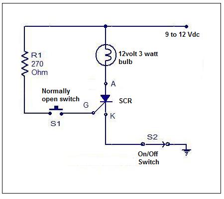
Although SCRs and TRIACs are not present in all electronic equipment, they are significant components. Understanding how to test them is essential for troubleshooting. Testing these components can be done with meters, but using an SCR/TRIAC tester is generally...
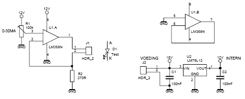
This led tester uses a power switched op-amp. The control range is about 0-30mA. Thus, all test and standard LEDs, the voltage across the LED to read. The power supply is an example lab power supply at least 15V,...
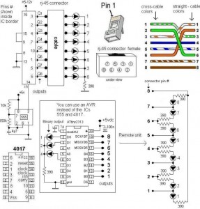
A LAN tester circuit diagram is presented in two designs. The first design utilizes a timer IC 555 and a decade counter 4017. The second design employs a microcontroller ATtiny2313. The first design of the LAN tester circuit incorporates the...
The circuit illustrated in Figure 555 represents a DC capacitor tester. This tester includes a pulse generator, a single-shot circuit, and a head indicating DC amplifier circuit. It is capable of measuring capacitance in the range of nanofarads (nF)...
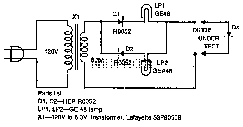
The circuit tests whether a diode is open, shorted, or functioning correctly. If lamp A lights, the diode under test is functional. When lamp B is lit, the diode is good but connected backwards. When both lamps are lit,...
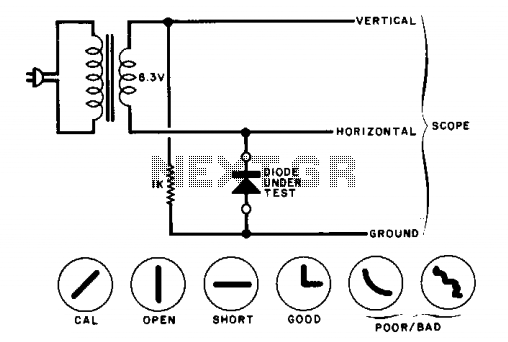
The circuit will display curves on an oscilloscope, depending on the state of the diode. To calibrate, replace the diode with a 1000-ohm resistor and adjust the oscilloscope gains for a 45-degree line. The drawings illustrate some expected results. The...
Warning: include(partials/cookie-banner.php): Failed to open stream: Permission denied in /var/www/html/nextgr/view-circuit.php on line 713
Warning: include(): Failed opening 'partials/cookie-banner.php' for inclusion (include_path='.:/usr/share/php') in /var/www/html/nextgr/view-circuit.php on line 713