
CRYSTAL TESTER
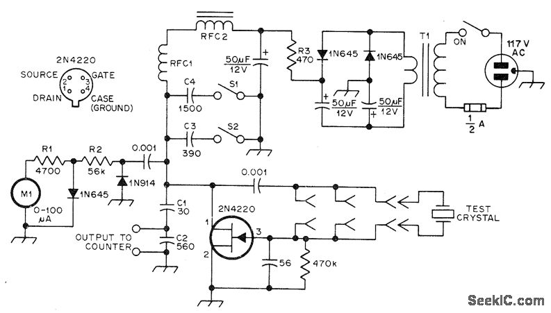
The JFET Pierce oscillator circuit is a versatile tool for evaluating crystal oscillators across a broad frequency spectrum. The oscillator employs a Junction Field Effect Transistor (JFET) in a Pierce configuration, which is characterized by its high-frequency stability and low phase noise. The design does not require tuning, making it user-friendly and efficient for quick testing of various crystals.
The oscillator's output transformer, T1, plays a critical role in impedance matching and signal amplification. Its high turns ratio of approximately 33:1 allows the circuit to efficiently drive connected measuring instruments, such as frequency counters, ensuring accurate frequency readings. The option to use a 6.3 V filament transformer highlights the circuit's flexibility in power supply configurations, facilitating the use of different rectifiers based on availability.
The inclusion of the 1N645 rectifiers provides a robust full-wave voltage doubling mechanism, converting the AC input into a stable 9 V DC output. This is essential for powering the oscillator and ensuring consistent operation across various test scenarios. The use of 50 µF filter capacitors further stabilizes the output voltage, reducing ripple and enhancing the performance of the oscillator.
Inductors RFC1 and RFC2 are integral to the circuit's functioning, with RFC1 providing a 2.5 mH inductance that aids in filtering and stabilizing the oscillator's output. RFC2, with its higher inductance of 150 mH, serves to further improve the circuit's performance by minimizing noise and enhancing signal integrity. The use of miniature toroidal inductors is advantageous due to their compact size and efficiency in high-frequency applications.
Overall, the JFET Pierce oscillator circuit is a sophisticated and effective solution for testing a wide range of crystal frequencies, making it an invaluable tool for electronics engineers and hobbyists alike. Its design prioritizes performance, reliability, and ease of use, ensuring accurate and efficient measurements of crystal oscillators.JFET Pierce oscillator will test any crystal from 50 kHz through 25-MHz upper frequency limit of fundamental-mode crystals without tuning, and drive counter for measuring crystal frequency, Will test overtone VHF crystals on their fundamental frequency. T1 is small output transformer from tube-type radio, having about 33: 1 turns ratio, or 6. 3-V f ilament transformer if 1N645 rectifiers are used in place of 50- F filter capacitors to give fullwave voltage doubler providing required 9 V. RFC1 is 2. 5 mH, and RFC2 is 150-mH miniature toroid. -F. Brown, A Universal Crystal Oscillator, QST, Feb. 1978, p 15-16. 🔗 External reference
Related Circuits
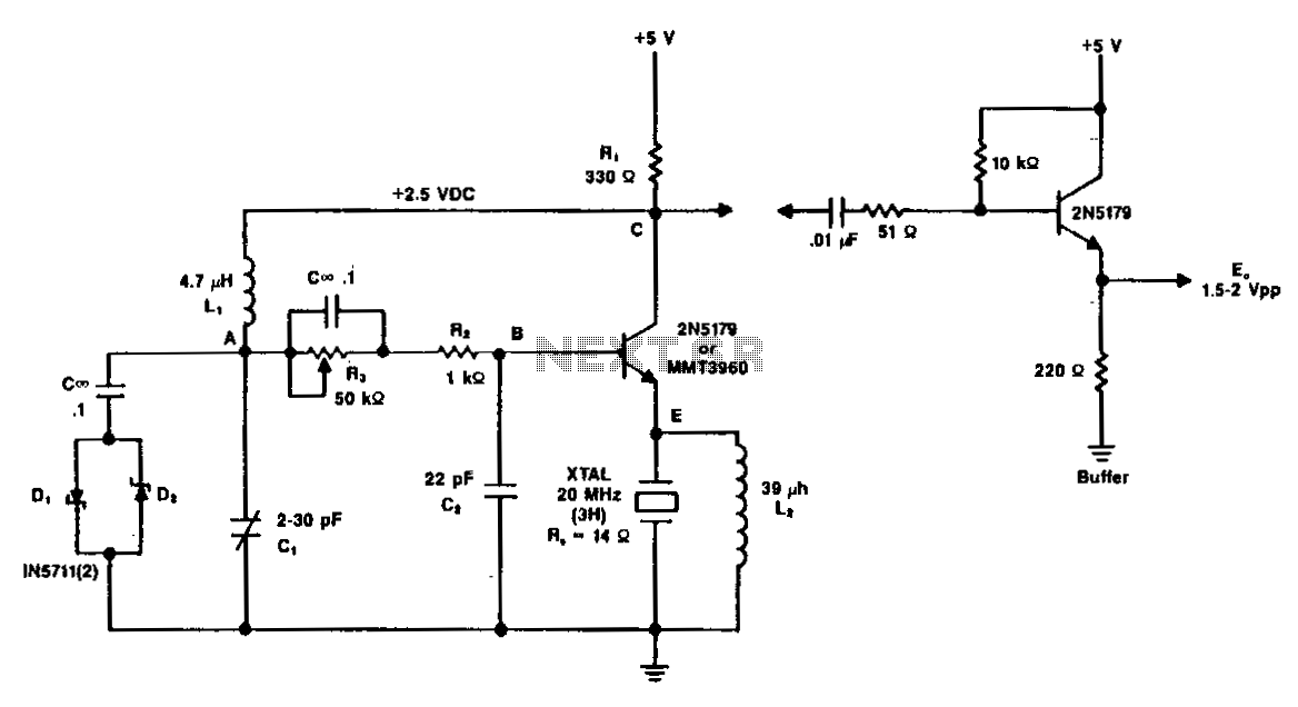
A typical circuit operating at 20 MHz is illustrated. The crystal, featuring an internal series resistance (Rs) of 14 ohms, oscillates at its third harmonic frequency. Diode clamps D1 and D2 ensure constant amplitude control. The transistor functions continuously...
The schematic below illustrates the division of a crystal oscillator signal by the crystal frequency to obtain an accurate 1-second time base with a precision of 0.01%. Two cascaded 12-stage counters (CD4040) form a 24-stage binary counter, and the...
This circuit utilizes a single 555 Timer IC and a small transformer to generate high voltage for testing zener diodes with voltage ratings up to 50VDC. The 555 Timer is configured in astable mode, with the output from pin...
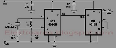
This circuit is designed for accurate time-base generation utilizing the commonly available 3.5795 MHz crystal, which is frequently used in telecommunication equipment. A crystal-based oscillator combined with a divider IC chain or a similar circuit, such as an ASIC,...
The RF engineer often needs an instrument that can reliably and quickly check a low-frequency quartz crystal unit. However, such equipment is challenging to find, and engineers frequently refer to electronic circuit handbooks for schematics that can perform this...
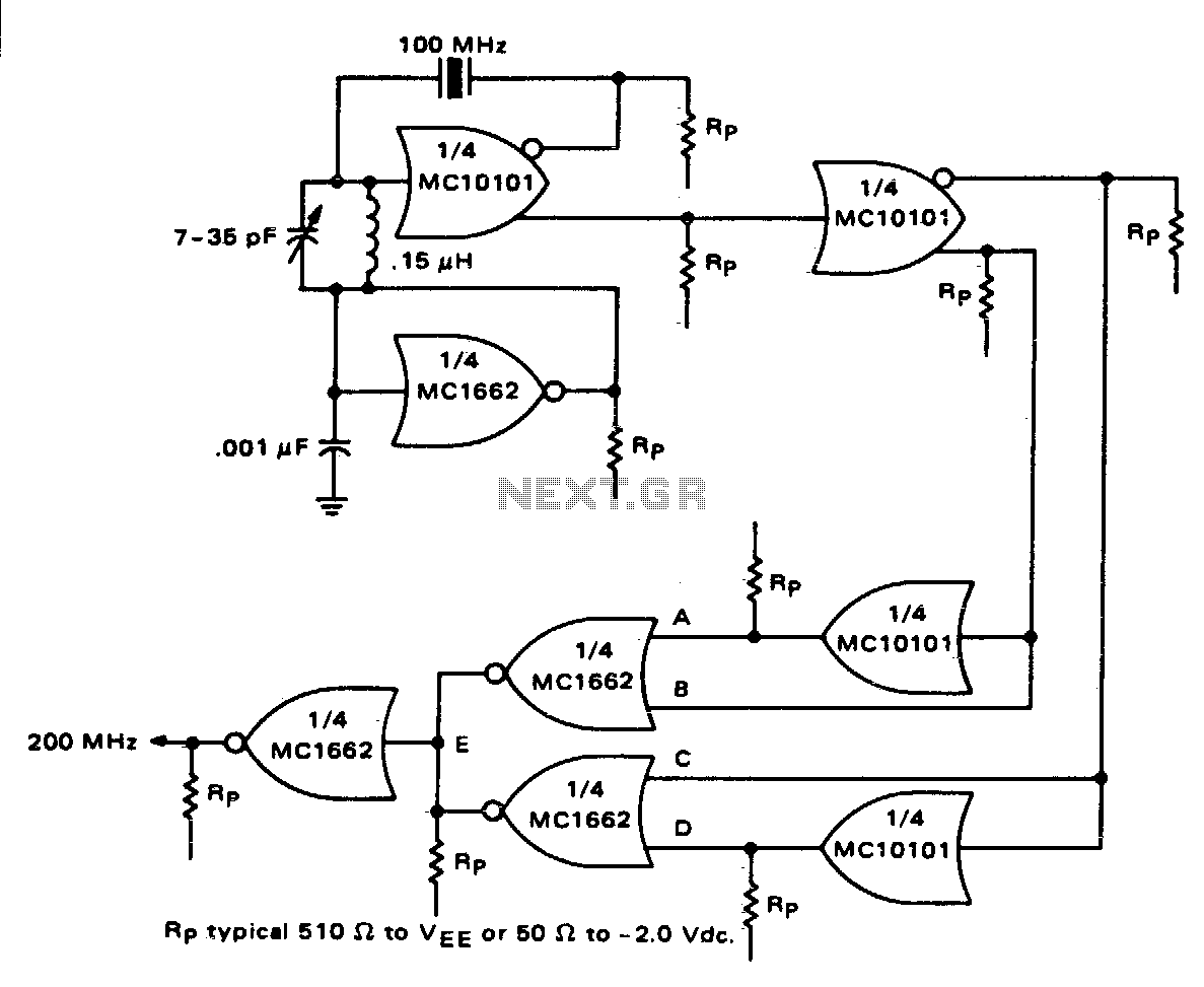
One section of the MC10101 is configured as a 100 MHz crystal oscillator, with the crystal placed in series within the feedback loop. An LC tank circuit is utilized to tune the 100 MHz harmonic of the crystal, which...