
CS9482 holiday lights ASIC
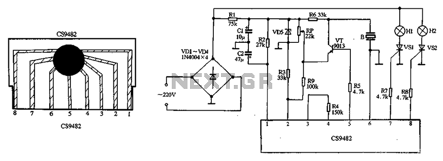
The CS9482 integrated circuit is a versatile component designed for applications such as decorative lighting and sound generation, particularly suitable for holiday displays. The integrated voltage regulator within the CS9482 ensures stable operation at 4.1V, which is critical for maintaining consistent performance of the circuit. However, when integrating additional components that may exceed this voltage threshold, it is essential to incorporate a current-limiting resistor (R2) to prevent damage to the circuit and ensure safe operation.
The VT manifold serves a dual purpose in this configuration; it not only amplifies the audio signal but also facilitates the driving of a piezoelectric ceramic sheet (B). This component is responsible for converting electrical signals into audible sound, enhancing the overall experience of the holiday lights display by synchronizing light patterns with music.
The electrical locator (VD5) plays a pivotal role in the circuit by allowing for fine-tuning of the transistor (VT) operating voltage. This adjustment is critical for optimizing performance and ensuring that the transistor operates within its specified parameters. Omitting this component could lead to suboptimal performance or even circuit failure.
The operational dynamics of the circuit are such that once the power is applied, the lantern strings (H1, H2) will exhibit a flashing light pattern, creating a visually appealing effect. Simultaneously, the piezoelectric ceramic chip (B) will produce electronic music, contributing to the festive atmosphere. The combination of light and sound in this circuit exemplifies the integration of electronic components to create an engaging and interactive experience. CS9482 integrated circuit fabrication with holiday lights circuit shown in Figure 2-37. Since the CS9482 chip already has 4.1V voltage regulator circuit, the external circuit m ay not necessarily be so regulated, but the voltage exceeds 4V, the external circuit should be added to the current limiting resistor R2. VT Manifold 5 feet for amplifying the output of the music signal to drive the piezoelectric ceramic sheet B sound.
FIG regulator VD5 electrical locator RP is mainly used to adjust the operating voltage of the transistor VT, VD5 can not be omitted. After the circuit is powered, lantern string HI, H2 can flashing light, while the piezoelectric ceramic chip B also plays electronic music within the reservoir.
Related Circuits

An emergency light is a light source designed to be available during emergencies. It operates automatically and is powered by a rechargeable battery. An emergency light system typically consists of several key components: a light source, a rechargeable battery, a...

AM radio receivers demodulate amplitude-modulated (AM) signals. The primary source of these signals is the Standard AM Radio Broadcast Band, although shortwave stations also utilize AM modulation. Amplitude modulation was developed between 1900 and 1917 by amateur radio enthusiasts....

The circuit operates on 220V AC, utilizing resistors R1 and R2 to create a partial voltage drop. A VD half-wave rectifier converts this AC voltage to approximately 3V DC across capacitor C. An adjustment potentiometer RP is incorporated to...

The following circuit illustrates a basic monostable multivibrator, which is based on the 555 Timer IC. Key features include pin 4 functioning as the RESET pin, with the time period defined by the equation t = R1 x C1. The...

The circuit features an AC input from VDI, which is converted to pulsating DC power using a VD4 full-wave bridge rectifier to power four lights. Resistors R1 and R2, along with diode VD5, form a simple circuit, while VD6...
The relay control allows for multiple pairs of contacts to be connected in parallel, enabling the circuit to handle a large lamp power. The design is straightforward; by simply changing the capacitance of the capacitor, different flash frequencies can...