
current controlled oscillator
The circuit operates by utilizing the principle of inductive saturation, where the inductance of the toroidal core decreases as the magnetic field strength increases due to the applied current. The oscillator circuit can be designed using a feedback configuration that incorporates the inductance of the toroid, allowing the frequency to vary in response to changes in the controlling current.
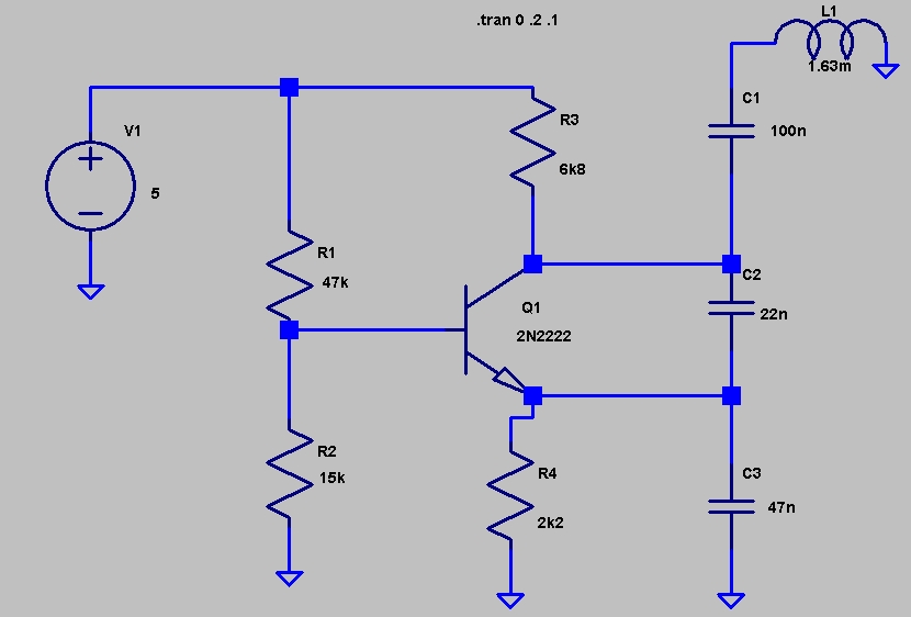
The oscillator can be constructed using a basic feedback oscillator topology, such as a Colpitts or Hartley oscillator, where the inductance of the toroid is a key component in determining the oscillation frequency. The frequency of oscillation (f) can be expressed as:
f = 1 / (2π√(L * C))
where L is the inductance and C is the capacitance in the circuit. As the current through the secondary winding increases, the inductance L decreases due to saturation effects, resulting in a higher frequency output.
The choice of the toroid core material and geometry is critical for achieving the desired inductance values and saturation characteristics. The FT37-43 core is a ferrite material that offers a good balance of inductance and saturation properties for this application.
In practical implementation, the circuit should include a method for measuring the output frequency, such as a frequency counter or an oscilloscope, to monitor the changes in frequency corresponding to the applied current. The use of a variable power supply can facilitate experimentation with different supply voltages to optimize circuit performance.
Overall, this circuit presents a valuable tool for exploring the behavior of inductors under varying current conditions and can serve applications in current sensing, feedback control systems, and educational demonstrations on magnetic saturation phenomena.This circuit was in EDN`s "design ideas" section in the March 5, 2007 issue. It`s a fairly simple circuit and an easy way to investigate how the inductance of a toroid (or any core) is changed by saturation, which in this case is caused by applying a current to a secondary winding. With this circuit, the oscillator frequency is a function of the co ntrolling current and so it can be used to measure current without direct ohmic connection to the circuit. I originally used 16 turns on an FT37-43 toroid for about 100uH, but it wouldn`t oscillate until I increased supply voltage from 5 to about 12 volts, and applying the measurement current would stop oscillation.
The frequency was over 150kHz. I did a new coil using a slightly larger FT37-43 with 50+ turns to give 1. 63mH. I wound four turns onto the toroid for the measurement winding. Frequency would move around (rise) after each adjustment, either due to some time constant or because current was changing below the 0. 4 A-t level. (100mA on the meter times four turns. ) Supply voltage was 5. 07 VDC. In some cases it seems to do better with higher supply voltage. The article hinted that this technique wouldn`t be repeatable enough for an accurate current measurement technique.
That`s probably true. For order-of-magnitude measurements or detection of overcurrent, it would be fine. It could also be used in a feedback loop (PLL) to control frequency using current and inductance as opposed to the traditional varactor method. This measurement could also be used to infer the inductance (and permeability) changes with current. In my example, 4 ampere-turns approximately doubled the frequency. Since frequency is proportional to the square root of inductance, the inductance was reduced by a factor of four (4).
🔗 External reference
Related Circuits
The variations, which effectively form an alternating signal, will be transmitted through the coupling capacitor to the subsequent stage, indicated by the arrow to the right. One variable resistor can be substituted with another. R1 can be replaced with...
A current loop transmitter refers to a sensor system utilized in industrial 4-20mA current loop technology. This transmitter contains the... A current loop transmitter is a critical component in industrial automation and control systems, particularly in applications where analog signal...
A brief note explaining the process of substituting crystal and ceramic resonator clock circuits with silicon oscillators, while emphasizing the technical benefits these devices provide in microcontroller clock applications. Silicon oscillators serve as an effective alternative to traditional crystal and...
A low-cost converter is capable of supplying constant AC currents up to 1 A over variable loads. The low-cost converter is designed to provide a stable output of alternating current (AC) while accommodating fluctuating load conditions. This capability is essential...
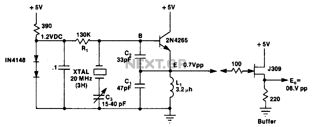
L1 and C1 are selected to resonate at a frequency below the desired crystal harmonic but above the crystal's next lower odd harmonic. Capacitor C2 should have a value between 30-70 pF, independent of the oscillation frequency. There is...
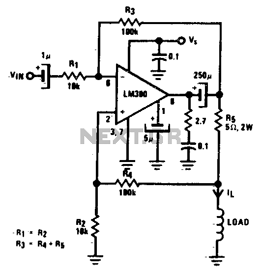
This circuit is one of the simplest voltage-to-current converters designed to drive low loads. In this example, a small 0.25-watt speaker with an 8-ohm resistance is utilized. It is suitable for microcontroller applications or any circuit that employs PWM...