
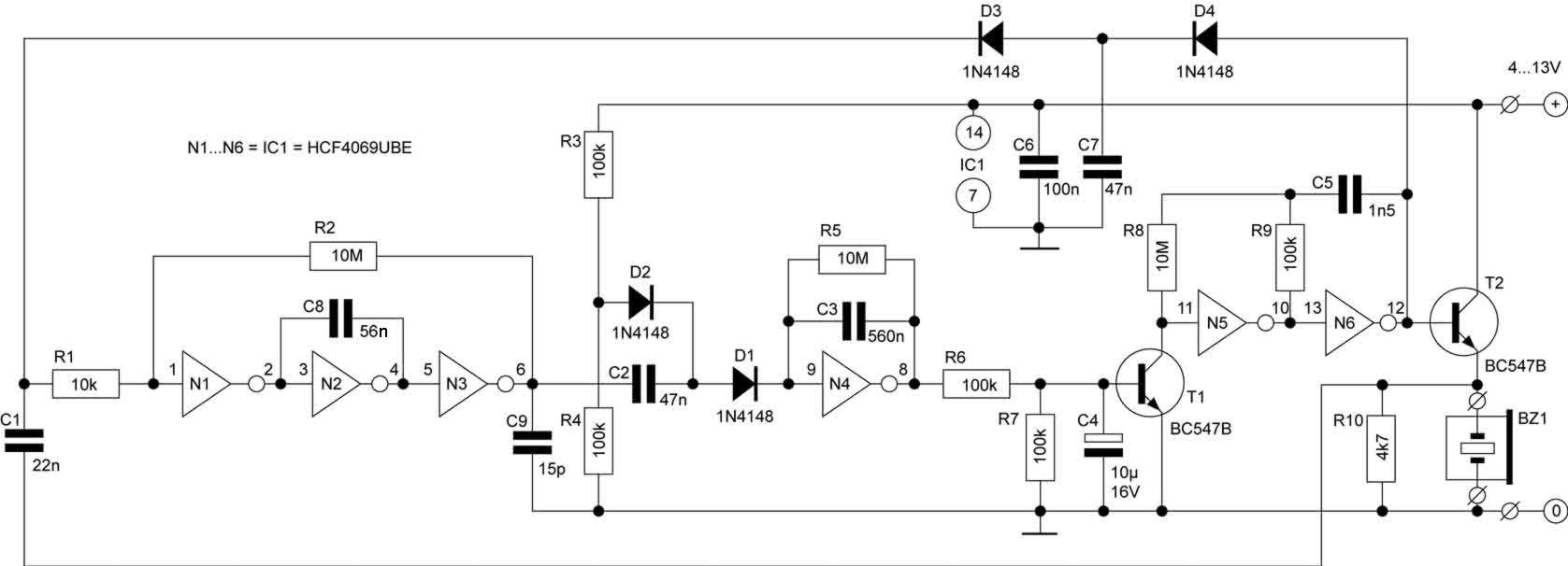
Current-Driven Sallen Key FilterCircuit
The Sallen-Key filter is a widely used active filter topology that employs operational amplifiers (op-amps) to achieve desired filtering characteristics. The current-driven variant of the Sallen-Key filter enhances performance by utilizing a current source instead of a voltage source, which can improve linearity and reduce distortion in audio applications.
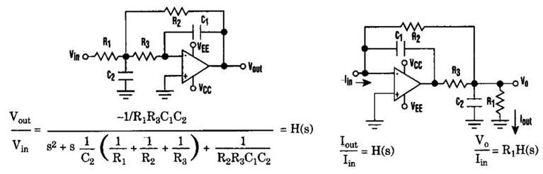
In a typical Sallen-Key low-pass filter configuration, two resistors and two capacitors are arranged in a manner that defines the cutoff frequency and the quality factor (Q) of the filter. The op-amp serves as a voltage follower, providing high input impedance and low output impedance, which is essential for maintaining the integrity of the signal being filtered.
The circuit can be described as follows:
1. **Components**: The essential components of the current-driven Sallen-Key filter include two resistors (R1 and R2), two capacitors (C1 and C2), and an operational amplifier (U1). Additionally, a current source (I) is used to drive the input signal.
2. **Configuration**: The first capacitor (C1) is connected to the non-inverting input of the op-amp, while the second capacitor (C2) is connected in feedback from the output to the inverting input. The resistors (R1 and R2) are placed in series with the capacitors to set the filter characteristics.
3. **Transfer Function**: The transfer function of the filter can be derived from the component values and describes how the output signal relates to the input signal across different frequencies. The cutoff frequency (fc) is determined by the formula:
\[
f_c = \frac{1}{2\pi\sqrt{R1 \cdot R2 \cdot C1 \cdot C2}}
\]
This relationship allows designers to choose component values to achieve the desired frequency response.
4. **Applications**: The current-driven Sallen-Key low-pass filter is particularly useful in audio processing, signal conditioning, and data acquisition systems, where clean and precise filtering of signals is critical.
5. **Advantages**: The primary advantages of this filter topology include simplicity in design, ease of implementation, and the ability to achieve high performance with minimal component count. The use of a current source can also offer improved performance characteristics compared to traditional voltage-driven filters.
This Sallen-Key filter design exemplifies a balance between simplicity and functionality, making it a preferred choice in various electronic applications.Current-Driven Sallen Key Filter Circuit Diagram he low-pass Sallen-Key filter is staple for designers because it contains few components (A). By redesigning the filter, 🔗 External reference
Related Circuits
This switch will suit the Modular Burglar Alarm circuit. However, it also has other applications. The Keypad must be the kind with a common terminal and a separate connection for each key. On a 12-key pad, look for 13...
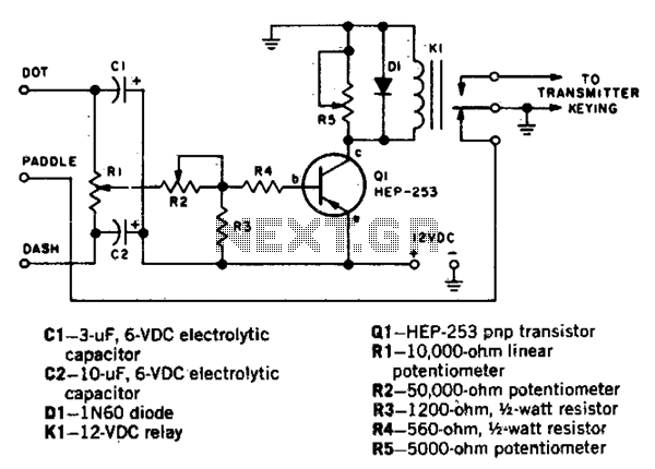
This circuit automatically generates Morse code dots and dashes determined by time constants involving C1 and C2. R1 establishes the dot/dash ratio, while R2 controls the speed. Additionally, R5 determines the relay drop-out point. The circuit functions by utilizing capacitors...
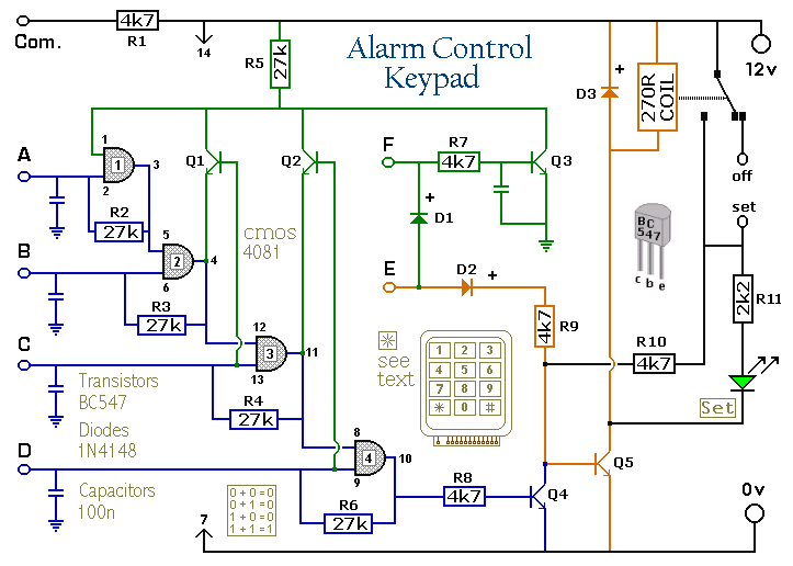
The keypad must be of the type that has a common terminal and a separate connection for each key. For a 12-key pad, there should be a total of 13 terminals. The matrix type with 7 terminals is not...
The task involves reading input from a keypad and displaying the corresponding button pressed on a 7-segment display. A C program is required to determine which key has been pressed on the keypad, and then display the corresponding character...
Picture a morning where you are anxiously waiting for the bus to work, only to realize that you cannot find your keys. If this scenario occurs often, this circuit is designed for you. A simple press of a button...
Frequency Shift Keying (FSK) refers to the method of transmitting digital data over a signal path, which can include two wires, telephone lines, or AM/FM transmitters. Typically, two signals are transmitted: one corresponding to a logical '1' and the...
Warning: include(partials/cookie-banner.php): Failed to open stream: Permission denied in /var/www/html/nextgr/view-circuit.php on line 713
Warning: include(): Failed opening 'partials/cookie-banner.php' for inclusion (include_path='.:/usr/share/php') in /var/www/html/nextgr/view-circuit.php on line 713