
Enhanced 4 Digit Alarm Keypad

The described circuit functions as a secure alarm system utilizing a keypad interface for activation and deactivation. The choice of a keypad with a common terminal and independent key connections allows for a flexible design that supports a wide range of codes. The use of a quad 2-input AND gate (CMOS 4081) for logic processing ensures that the alarm can only be deactivated with the correct sequence of key presses, providing a safeguard against unauthorized access.
The circuit's design incorporates a relay for the alarm mechanism, which is energized by the output of the AND gates. The relay's ability to hold its state is critical for maintaining the alarm's active status until the correct deactivation sequence is entered. The inclusion of diodes and resistors in the circuit helps to manage the current flow and protect the components from potential damage due to incorrect key presses.
The system's flexibility is enhanced by the option to change the keypad connections, allowing users to customize their security codes easily. The potential for using a larger keypad increases the complexity of the code, providing an additional layer of security. The layout of components on the circuit board, including the strategic placement of links and the requirement for certain links to be installed before the IC, reflects careful consideration of assembly and functionality.
In summary, this circuit design effectively combines keypad input with logical processing to create a robust alarm system, capable of supporting a high degree of customization while ensuring security through a structured deactivation protocol.The Keypad must be the kind with a common terminal and a separate connection for each key. On a 12-key pad, look for 13 terminals. The matrix type with 7 terminals will NOT do. The Alarm is set by pressing a single key. Choose the key you want to use and wire it to `E`. Choose the four keys you want to use to switch the alarm off, and connect them to `A B C & D`. Your code can include the non-numeric symbols. With a 12-key pad, over 10 000 different codes are available. Wire the common to R1 and all the remaining keys to `F`. When `E` is pressed, current through D2 and R9 switches Q5 on. The relay energises, and then holds itself on by providing base current for Q5 through R10. The 12-volt output is switched from the "off " to the "set " terminal, and the LED lights. To switch the Alarm off again it is necessary to press A, B, C & D in the right order. The IC is a quad 2-input AND gate, a Cmos 4081. These gates only produce a high output when both inputs are high. Pin 1 is held high by R5. This `enables` gate 1, so that when `A` is pressed, the output at pin 3 will go high. This output does two jobs. It locks itself high using R2 and it enables gate 2 by taking pin 5 high. The remaining gates operate in the same way, each locking itself on through a resistor and enabling its successor. If the correct code is entered, pin 10 will switch Q4 on and so connect the base of Q5 to ground. This causes Q5 to switch off and the relay to drop out. Any keys not wired to `A B C D or E` are connected to the base of Q3 by R7. Whenever one of these `wrong` keys is pressed, Q3 takes pin 1 low. This removes the `enable` from gate 1, and the code entry process fails. If `C` or `D` is pressed out of sequence, Q1 or Q2 will also take pin 1 low, with the same result. You can change the code by altering the keypad connections. If you need a more secure code use a bigger keypad with more `wrong` keys wired to `F`. A 16-key pad gives over 40 000 different codes. All components are shown lying flat on the board; but some are actually mounted upright. The links are bare copper wires on the component side. Two of the links must be fitted before the IC. The Support Material for this circuit includes a step-by-step guide to the construction of the circuit-board, a parts list, a detailed circuit description and more.
🔗 External reference
Related Circuits

The features accessible through the keypad are detailed in the Spectrum128 Introduction Manual, which was provided with each unit sold. The service manual for the Spectrum128 is intended for repair technicians and outlines the circuitry and communication protocol utilized...

Construct a digital multimeter capable of measuring DC and AC voltages up to 100V and DC and AC currents up to 1A. The circuit will be powered by a 9V battery. The design incorporates a modified voltmeter to suit...

This tutorial on the PIC16F877 microcontroller addresses the question, "How to implement a digital clock using the PIC16F877?" The use of the PIC16 simulator (Proteus) is included. The PIC16F877 microcontroller is a versatile and widely used component in embedded systems,...

This circuit utilizes invisible infrared light to detect the movement of individuals through a doorway. A brief beep will be emitted when the infrared beam is interrupted. The infrared movement detection circuit employs an infrared LED and a photodiode or...

AD7710/7715/7730 multifunction digital sensor signal conditioning integrated circuits (ICs) that combine a digital interface with a control port, a clock generator, a digital filter, amplitude modulation, a programmable gain amplifier, an analog-to-digital (A/D) converter, and additional electrical pathways. The...
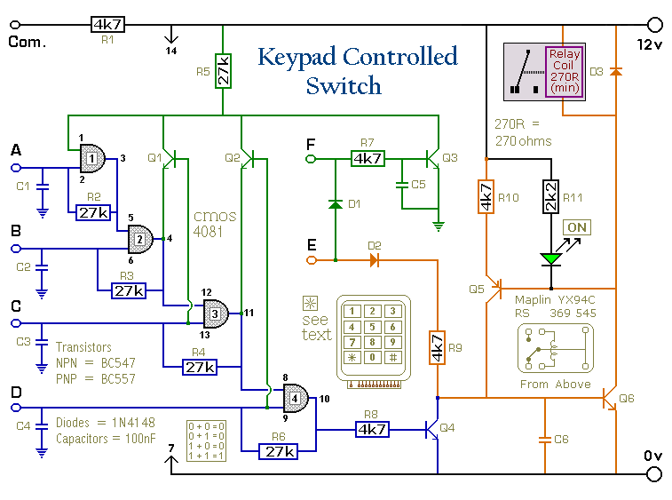
This is a universal version of the Four-Digit Alarm Keypad. The design of the output section has been modified to free up the relay contacts, allowing the circuit to function as a general-purpose switch. A single-pole changeover (SPCO) or...