
Keypad Scan
The circuit schematic for this project outlines the connections between the 8051 microcontroller and the keypad as well as the 7-segment display. The keypad is interfaced with the microcontroller through its port pins. Each column of the keypad is connected to one of the microcontroller's output pins, while the rows are connected to input pins that can read the state of each button. The 7-segment display is also connected to a set of output pins on the microcontroller, allowing it to display the appropriate digit or character based on the key pressed.
The microcontroller utilizes a scanning technique to detect key presses. It sequentially sets one of the four rows to a low state while keeping the others high. Following this, it checks the columns to identify if any key in the active row is pressed. If a button is pressed, the corresponding row pin will read low, indicating a connection between the active column and the pressed button. This information is then used to determine which key was pressed.
The program includes a lookup table for converting the key position into the corresponding output for the 7-segment display. The conversion table maps each key's position to a specific value that corresponds to the segments needed to display the correct character on the 7-segment display. Special characters such as '*' and '#' are handled separately, as they do not correspond to valid display outputs.
Overall, this implementation provides a straightforward method for interfacing a keypad with a microcontroller to display the pressed keys on a 7-segment display, leveraging basic principles of input scanning and output control in embedded systems.You will be reading input from a keypad and display the corresponding button pressed unto a 7-segment display. You will be required to write a C program which will determine which key has been pressed on the key pad.
The program will then display the corresponding character by configuring the output port correctly. The program will be compiled using the C51 compiler and burned onto an 8051 chip. A schematic is provided below to show connections needed to implement this lab. Keypads are often used as a primary input device for embedded microcontrollers. The keypads actually consist of a number of switches, connected in a row/column arrangement as shown in Fig 2. In order for the microcontroller to scan the keypad, it outputs a nibble to force one (only one) of the columns low and then reads the rows to see if any buttons in that column have been pressed.
The rows are pulled up by the internal weak pull-ups in the 8051 ports. Consequently, as long as no buttons are pressed, the microcontroller sees a logic high on each of the pins attached to the keypad rows. The nibble driven onto the columns always contains only a single 0. The only way the microcontroller can find a 0 on any row pin is for the keypad button to be pressed that connects the column set to 0 to a row.
The controller knows which column is at a 0-level and which row reads 0, allowing it to determine which key is pressed. For the keypad, the pins from left to right are: R1, R2, R3, R4, C1, C2, C3, C4. /* main. c */ /* Read from a keypad and display the key pressed */ /* on an 7-segment display */ #pragma SMALL DB OE #include
h> unsigned char SetDisplay(unsigned char value){ unsigned char LookupTable[17] = { 0xC0, . }; /* use code from previous lab */ /* fill in entries to table to handle A, B, C, D, E, F */ } /* Routine to scan the key pressed */ unsigned char key_scan() { unsigned char i, j, temp1, temp2; while( 1 ) /* keep waiting for a key to be pressed */ for(i=0; i<4; i+) { /* Set each row to 0 */ P1="0xff" & ~(1<
🔗 External reference
Related Circuits
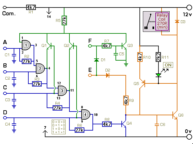
The key connected to "E" is used to energize the relay, while the four keys connected to A, B, C, and D are used to de-energize it. All other keys on the keypad are connected to "F". When "E"...
The CDCF5801 provides clock multiplication from a reference clock (REFCLK) signal with the unique capability to delay or advance the CLKOUT/CLKOUTB with steps of only 1.3 mUI through a phase aligner. For every rising edge on the DLYCTRL pin,...

This circuit is designed for use with a Universal Keypad Operated Switch. A few genuine mistakes made during code entry will not activate the device. However, repeated attempts to input the correct code through trial and error will cause...
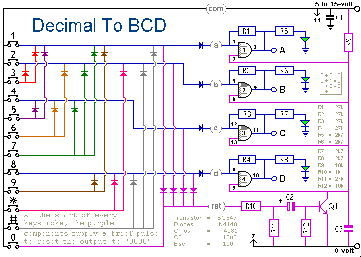
When a keypad switch is pressed, this circuit reproduces its value in Binary Coded Decimal (BCD) format. A 12-keypad is used, but it can be expanded to 16 keys for Hexadecimal to BCD conversion. The circuit consists of two...

This circuit is designed to operate an electrical door-release mechanism, but it can also be used for other applications. Users can enter a four-digit code of their choice, which will energize a relay for a duration determined by the...

The low-cost Mini-Circuits MAR-X series of chips provides a significant advantage for RF builders, featuring inherent 50-ohm input and output impedances essential for RF systems. An MAR-1-based receiver/scanner preamplifier is illustrated. Capacitors Ci and C2 are chip capacitors, with...
Warning: include(partials/cookie-banner.php): Failed to open stream: Permission denied in /var/www/html/nextgr/view-circuit.php on line 713
Warning: include(): Failed opening 'partials/cookie-banner.php' for inclusion (include_path='.:/usr/share/php') in /var/www/html/nextgr/view-circuit.php on line 713