
Automatic lighting switch circuit
The NE555 timer is a versatile integrated circuit used for generating precise timing and oscillation. In this circuit, it operates in a comparator mode, where the photosensitive resistor (RG) serves as an input to determine the ambient light level. The SSR provides the capability to control high-voltage AC loads safely, isolating the control circuit from the AC mains.
The design begins with the photosensitive resistor RG, which is connected in such a way that its resistance varies with the intensity of light. During daylight, RG's low resistance keeps the voltage at the NE555's threshold pin high, preventing the output from switching. As darkness sets in, RG's resistance increases, dropping the voltage at the threshold pin below the reference level set by the NE555. This transition triggers the timer's output to switch from low to high.
The output from the NE555 drives the gate of the SSR, which is rated to handle the required AC load. The SSR acts as an electronic switch, allowing current to flow through the connected incandescent light when activated. The inclusion of an adjustable potentiometer (RP) allows users to set the sensitivity of the light detection, effectively determining the light level at which the circuit activates the light. This feature enhances the circuit's usability in various lighting conditions.
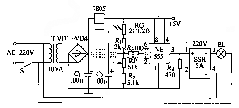
Overall, this automatic light switch circuit provides a practical solution for controlling lighting based on ambient light levels, utilizing the NE555 timer and SSR for efficient operation and reliability.NE555 time base circuit with AC solid state relay SSR may constitute automatic light switch circuit, the circuit shown in FIG. From the figure can be seen during the day due to incandescent EL photosensitive resistor circuit automatically fall off when the
night. EL turn on automatically. in graph. RG photosensitive resistance 2CU2B. When RG by light, resistance becomes smaller, when added to the base circuit NE555, pin voltage is higher, so the output of NE555 is low, the AC solid state relay SSR deadline, according to the AU does not light. When night falls, RG resistance increases, NE555 of, voltage is below 5v. @ The output pin goes high, the AC solid state relay SSR device of O feet to obtain a positive power source is turned on, it controlled AC output terminal, turned on.
EL incandescent lighting, adjustment potentiometer RP, can change the lighting to the light switch time.
Related Circuits
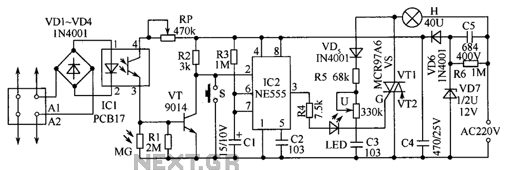
The telephone table lamp is designed to automatically illuminate during night ringing or when the phone is off-hook. After hanging up, the lamp will extinguish after a delay of 45 seconds. It is typically used as a general-purpose lamp...
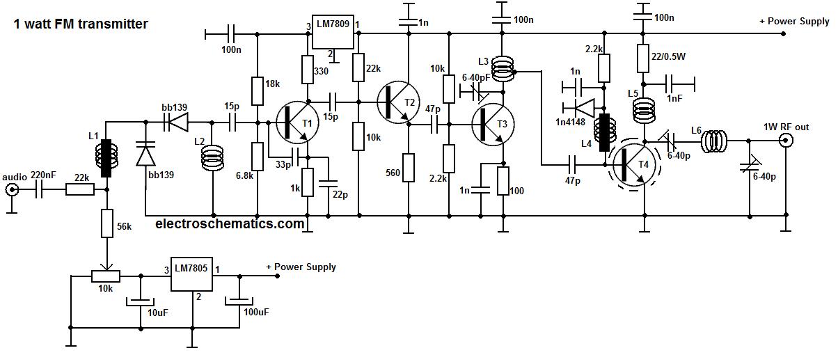
This portable FM transmitter features a limiter, a microphone amplifier, and PLL digital tuning, all integrated onto a single circuit board. The RF power output can be switched between 1 W (high) and 0.2 W (low). The schematic is...
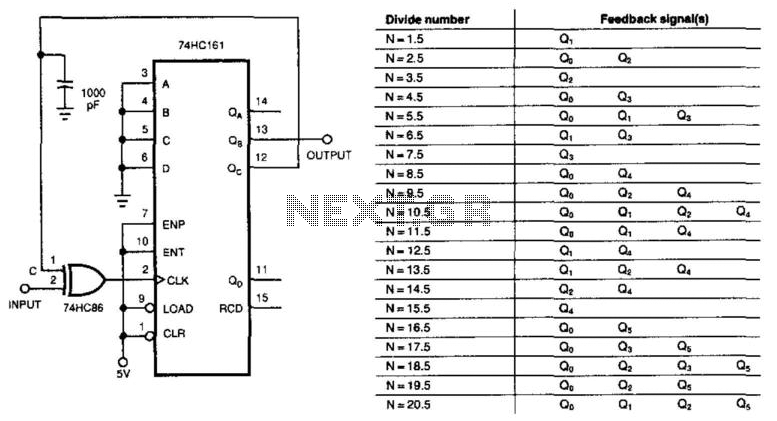
This circuit divides the input signal by +1/2 instead of dividing by an integer. With the feedback connections as illustrated in the figure, the circuit effectively divides by 3.5. Point C ultimately determines when the input triggers the 74HC161...
This circuit provides automatic current limiting up to 8.4 A. Unlike current limiters that use only a resistor, this current limiting circuit does not drop the voltage significantly or keeps the voltage drop to a minimum until a specific...

This second-order low-pass filter utilizes a 741 operational amplifier and can be tuned from 2.5 kHz to 25 kHz. The circuit is beneficial in audio and tone control applications. R1 and R2 are ganged potentiometers. The described circuit features a...
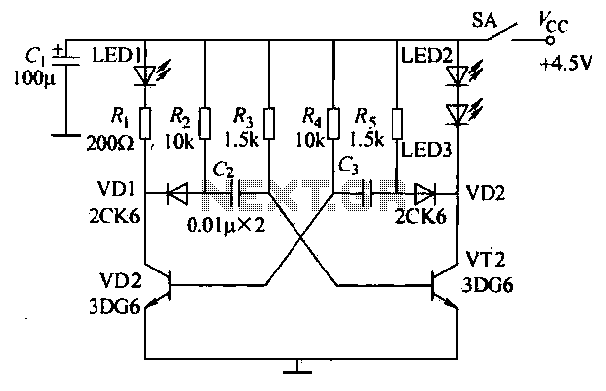
The infrared transmitter circuit, as depicted in Figure 18-la, utilizes transistors VT1 and VT2 along with RC components to create an astable multivibrator. The circuit operates with VT1 and VT2 receiving base bias from resistors, and closing switch SA...
Warning: include(partials/cookie-banner.php): Failed to open stream: Permission denied in /var/www/html/nextgr/view-circuit.php on line 713
Warning: include(): Failed opening 'partials/cookie-banner.php' for inclusion (include_path='.:/usr/share/php') in /var/www/html/nextgr/view-circuit.php on line 713