
sound via laser light
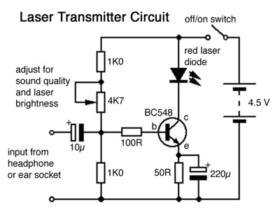
The described circuit modification enhances the functionality of a basic sound transmission system by utilizing a laser diode instead of a standard LED. The implementation involves careful selection of components to ensure compatibility and performance. The red laser diode, chosen for its visibility and efficiency, operates optimally at a voltage of 4.5V, which is safely within the recommended limits to prevent damage. The current draw of approximately 30 mA is manageable for the BC548 transistor, which acts as a switch to control the laser's operation based on audio input signals.
The method for removing the laser casing is a critical step, as it allows for better integration of the laser diode into the overall circuit. The use of a black plastic pen casing serves both aesthetic and functional purposes, providing a lightweight and sturdy housing for the laser component. The wooden blocks provide stability and allow for easy adjustment of the laser beam's position during setup.
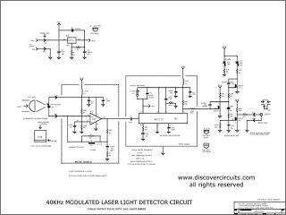
Additionally, the incorporation of an oscilloscope to visualize the output signals when a remote control is used adds an educational aspect to the project. It enables students to observe the modulation patterns generated by different button presses, reinforcing the concepts of digital signal transmission and modulation. This practical application of electronics not only enhances learning but also demonstrates the versatility of laser technology in communication systems. Overall, this circuit design exemplifies an effective approach to improving sound transmission distance while maintaining user engagement and educational value.The transmission distance can be increased greatly by replacing the transmitter`s red LED with a cheap red laser diode purchased from a $2 Dollar Shop . The circuit design makes a compromise between laser brightness and sound quality and loudness. This is because the laser needs to be bright enough so that it is easy to locate the beam when posi tioning the receiver and for students to see that the laser beam is really there and carrying` the sound. Do not apply any more than 5 volts to the laser diode. I find that 4. 5 volts from 3 AA cells works well. At that voltage the laser draws about 30 mA allowing a cheap general purpose NPN bipolar transistor (such as the BC548) to work well in modulating the current through the laser.
The laser casing needs to be removed. I cut carefully along the metal casing using a fine hacksaw and then prise it off the laser barrel with long-nosed pliers. The photo alongside shows the laser barrel inserted in a black plastic pen casing which is itself mounted in a small wooden block glued to the larger block.
This is particularly useful when a remote control is shone` at the receiver. Then the oscilloscope can display the different digital patterns when each of the remote control keys are pressed. 🔗 External reference
Related Circuits
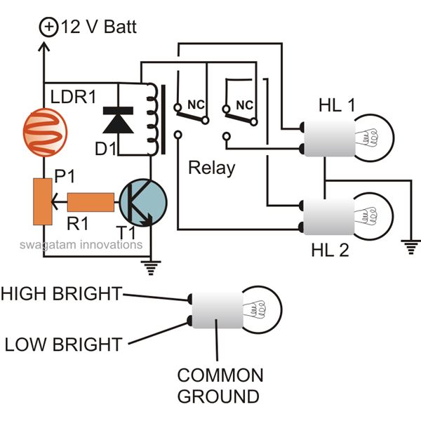
The circuit described here can be built and used in a vehicle for an automatic dipping and dimming operation of the headlamps in response to intense lights coming from opposite vehicle headlamps. This situation is often encountered while driving...
The circuit presented is an integrated circuit (IC) controlled emergency light. Its key features include automatic activation of the light during mains failure and a battery charger equipped with overcharge protection. In the absence of mains power, relay RL2...
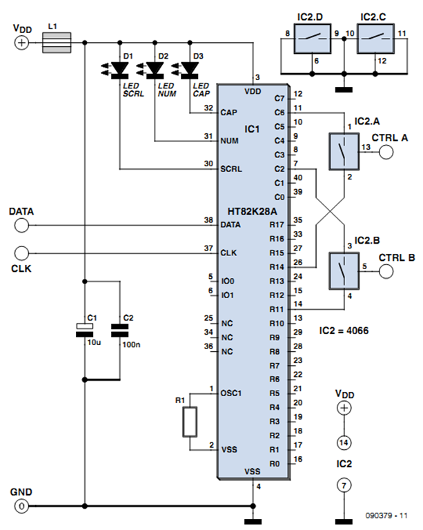
One of the more challenging aspects of creating a control or security system that utilizes a PC, such as a burglar alarm, is connecting the sensors to the computer. This typically requires specialized interface expansion boards, and programming that...
The circuit shown here is used to switch on a lamp when the telephone rings, if the ambient light is insufficient. The circuit uses only two ICs and it can be implemented very easily. A light dependent resistance (LDR),...
The circuit is divided into two sections: the isolated external loop connected to the remote interface connector on the front of the power supply unit (PSU) and the non-isolated inner loop connected to the high-tension (AC line) supply. The...
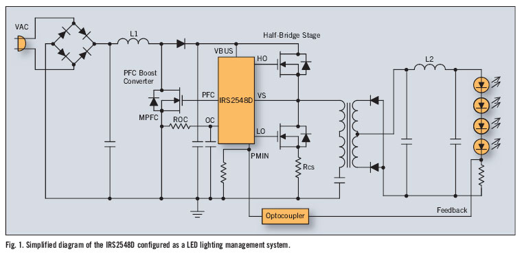
There is significant sensitivity to operating costs when managing high-powered commercial lighting. In these applications, there is a heightened focus on energy efficiency and AC line power factor, as these parameters influence operating expenses. Electric utilities impose additional charges...
Warning: include(partials/cookie-banner.php): Failed to open stream: Permission denied in /var/www/html/nextgr/view-circuit.php on line 713
Warning: include(): Failed opening 'partials/cookie-banner.php' for inclusion (include_path='.:/usr/share/php') in /var/www/html/nextgr/view-circuit.php on line 713