
Current Loop Sensor Interface
More: The throttle itself consists of a coil and some electronics with a steel jacketed brass slug which is moved in and out of the coil by the throttle movement. The assembly has only two contacts and draws a current of between 600 microamps and 2 milliamps: the current varies with slug position as the throttle is moved. As such it is a system which borrows much from the industrial 4-20mA current loop sensor standard.
The sensor will work down to about 5 to 6 volts minimum. 4QD's NCC and Pro-120 use an internal 9v rail, so there is not a huge 'overhead' to allow any voltage swing across the sensor, hence this circuit.
The sensor is shown by the standard symbol for a current source (two intersecting circles).
Tr1 and Tr2 are a current mirror arranged to source about 1mA into the sensor, via Tr2. This current can be adjusted by the preset to 'back-off' the zero position current. This allows an electrical zero adjust (in practise the customers usually prefer to use the throttle's mechanical zero adjust).
Tr3, 4 and 5 are a second mirror which reflect the sensor's output current (less the backed off zero portion) into the 4K7 resistor - a resistor is a current to voltage converter! We have therefore developed an output voltage proportional to throttle position and it has the same 3 wires as a standard potentiometer.
This circuit is designed to facilitate the integration of a current loop sensor, specifically a contactless throttle sensor, with existing voltage-based input systems, such as those found in motor controllers. The fundamental operation is based on the principle of current mirroring and conversion, where the throttle sensor's output current is accurately translated into a corresponding voltage signal.
The throttle sensor operates on the principle of inductance, utilizing a moving brass slug within a coil to modulate the current draw between 600 microamps and 2 milliamps, depending on the position of the slug. This current range is typical for industrial applications, aligning with the 4-20mA standard. The circuit is powered by a minimum of 5 to 6 volts, with the 9V rail from the 4QD motor controllers providing adequate voltage for operation without significant overhead.
The current mirror configuration, consisting of transistors Tr1 and Tr2, ensures a stable 1mA current is supplied to the sensor, with a preset adjustment allowing for fine-tuning of the zero position. The output from the sensor is processed by a second current mirror formed by transistors Tr3, Tr4, and Tr5. This arrangement reflects the sensor's output current, minus the adjusted zero current, through a 4.7kΩ resistor, effectively converting the current signal into a voltage output that is linearly proportional to the throttle position.
The output voltage is then compatible with standard potentiometer inputs, featuring three wires for easy integration with existing systems. This design allows for seamless interfacing and provides users with a straightforward method for implementing a modern throttle control solution in electric vehicle applications.This is a very simple circuit to interface a current loop sensor to an input which is designed for a voltage, such as that from a standard potentiometer. This page is technical so that interested persons can build the circuit themselves, but 4QD can also supply the interface on a 'postage stamp' sized (22mm x 27mm) board as shown in the first diagram.
It is a relatively trivial circuit! This circuit was developed to interface one of the new type contactless (inductive) throttle sensors to 4QD's motor controllers for use in a conversion to an Eze-Go golf car. The throttle itself consists of a coil and some electronics with a steel jacketed brass slug which is moved in and out of the coil by the throttle movement. The assembly has only two contacts and draws a current of between 600 microamps and 2 milliamps: the current varies with slug position as the throttle is moved.
As such it is a system which borrows much from the industrial 4-20mA current loop sensor standard. The sensor will work down to about 5 to 6 volts minimum. 4QD's NCC and Pro-120 use an internal 9v rail, so there is not a huge 'overhead' to allow any voltage swing across the sensor, hence this circuit. The sensor is shown by the standard symbol for a current source (two intersecting circles). Tr1 and Tr2 are a current mirror arranged to source about 1mA into the sensor, via Tr2. This current can be adjusted by the preset to 'back-off' the zero position current. This allows an electrical zero adjust (in practise the customers usually prefer to use the throttle's mechanical zero adjust).
Tr3, 4 and 5 are a second mirror which reflect the sensor's output current (less the backed off zero portion) into the 4K7 resistor - a resistor is a current to voltage converter! We have therefore developed an output voltage proportional to throttle position and it has the same 3 wires as a standard potentiometer.
🔗 External reference
Related Circuits
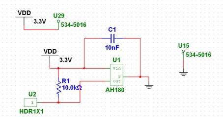
The chosen Hall Effect sensor is the AH180 Micropower Omnipolar Hall-Effect Sensor Switch. This sensor is utilized to detect the removal of a cup. The operational principle of the Hall Effect sensor involves outputting a high or low signal...
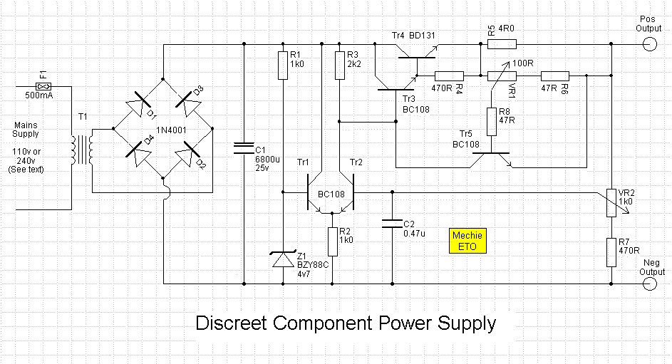
An error amplifier is constructed using transistors Tr1 and Tr2, configured as a differential amplifier, commonly referred to as a long-tailed pair, with the collector leads being a notable feature. One input of this differential amplifier is sourced from...

This is a design of the circuit diagram for an RS422 interface. Connector K1 is connected to the serial port of the PC, and power for the PC side of the circuit is obtained from the signal lines DTR...

The Proximity Sensor circuit is illustrated below. Three red boxes indicate the additions to the circuit previously constructed in Part 2: Motor Control. The new components included in the schematic are the GP2Y0A21YK IR Sensor, a headphone speaker, and...
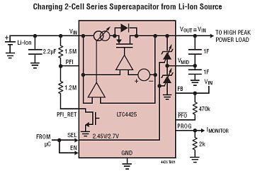
The LTC4425 is a constant-current/constant-voltage linear charger designed to charge a two-cell supercapacitor stack from a Li-Ion/Polymer battery, a USB port, or a current-limited supply ranging from 2.7V to 5.5V. This component functions as an ideal diode with a...
Have you ever wanted to create a line-following robot but found infrared sensors too expensive? If you are located in the UK and have access to a Maplin store nearby, you can purchase infrared transmitters and receivers for just...