
Hall_Effect Sensor
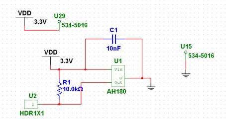
The AH180 Micropower Omnipolar Hall-Effect Sensor Switch is a compact and efficient device designed for low-power applications. Its omnipolar sensitivity allows it to detect magnetic fields from either pole of a magnet, making it versatile for various positioning and proximity sensing applications. The sensor operates on a supply voltage range typically from 2.5V to 3.6V, making it suitable for battery-operated devices.
In practical applications, the sensor's output can be directly interfaced with microcontrollers or other digital logic circuits. The output signal is typically a digital high when a magnetic field is present and transitions to a digital low in its absence. This behavior is suitable for applications such as cup detection, where the presence of a magnet can indicate whether the cup is in place or has been removed.
For optimal performance, it is crucial to ensure proper connections in the circuit. Any disconnection of the power supply lines or the output line can lead to malfunction, as observed during Integration 2. It is advisable to employ robust connectors and to verify all wiring before final assembly. Additionally, implementing a pull-up resistor on the output line may enhance signal integrity and prevent floating states when the sensor is not actively being driven.
The low current consumption of less than 1 mA allows for extended battery life in portable applications, making the AH180 an excellent choice for energy-sensitive designs. Overall, the integration of the AH180 Hall Effect sensor into a circuit requires careful consideration of mechanical assembly and electrical connections to ensure reliable operation in detecting magnetic fields.The Hall Effect sensor that was chosen was the AH180 Micropower Omnipolar Hall-Effect Sensor Switch. The Hall Effect was used to notify the cup that it was taken. The way the Hall Effect sensor works is it will either output a high or low signal depending on the presence of a magnetic flux density. If a high enough magnetic flux density is present , the output of the Hall effect sensor will be the same as the reference voltage applied to it. Without the magnet present, the output will be lower than the saturation voltage of the sensor. With a magnet mounted onto the fount under the cup, the Hall Effect sensor outputs a high into the PIC. When the pin connected to the output of the Hall Effect sensor goes low, the PIC throws a flag, and changes the status of the cup`s presence.
The Hall Effect sensor worked as a stand alone block, and with the rest of the blocks during Integration 1. Howerver the sensor did not function properly during Integration 2 when the circuitry was placed into the cup.
The majority of the hardware was not functioning after being placed into the cup. I believe that there were wires that became unconnected once the circuitry was placed into the cup. The 3. 3V line, the ground, or the output from the Hall Effect sensor could have become detached. If any of these things occurred, it would prevent the sensor from functioning properly. The Hall Effect sensor outputs a max of whatever reference voltage is input into it if a strong enough magnet is present. Otherwise the output is really close to 0 V. For our purposes, we used 3. 3 V for the Hall Effect sensor. The current pulled by the Hall Effect sensor is less than 1 mA. 🔗 External reference
Related Circuits

This light sensor switch circuit enables the automatic activation of a lamp when ambient light levels are low (such as during nightfall) and keeps the lamp illuminated for a specified duration. When transistors T4 and T5 are activated, the...
The following circuit illustrates a Robotics IR Navigation Sensor Circuit Diagram. Features include one chip, the 74HC04, and the IR sensor is designed to operate in direct sunlight. The Robotics IR Navigation Sensor Circuit utilizes an inverter IC, specifically the...
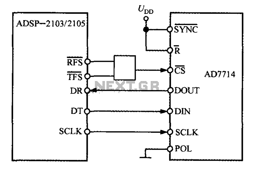
The ADSP-2103 and ADSP-2105 are digital signal processors that interface with the AD7714. When the output is active, the ADSP-2103/2105 configuration includes the RFS non-TES non-terminal set to a low level, while the SCLK terminal is configured for serial...
The following circuit illustrates a BC 547 transistor used in a garage alarm sensor circuit diagram. Features include a simple single-zone burglar alarm circuit. The BC 547 transistor is a popular NPN bipolar junction transistor (BJT) that is frequently used...
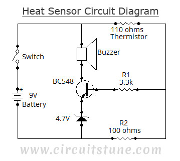
This simple heat sensor circuit can detect heat from various electronic devices such as computers and amplifiers, generating a warning alarm when overheating occurs. It can also sense heat from the environment, but it is primarily designed for use...
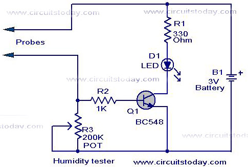
A simple humidity tester circuit using only an LED, a transistor, and a few resistors is explained with a clear circuit schematic. The humidity tester circuit is designed to provide a visual indication of humidity levels using basic electronic components....